12v Ignition Coil Ballast Resistor Wiring Diagram – The first step is to look at the various types of terminals for the ignition switch. These are the terminals for the Ignition, Coil, or Accessory. After we’ve identified the purpose of these terminals, we can recognize the various parts of the ignition wiring. We will also talk about the functions and the Coil. After that, we’ll turn our attention to Accessory terminals.
Ignition switch terminals
An ignition switch contains three different switches that direct the battery’s current to different destinations. The first switch is the one that supplies power to the choke while the second switch controls the state of the switch. Different manufacturers employ different color codes for different conductors. This is explained in a different article. OMC employs this system. The adapter is attached to the ignition switch to allow the addition of a tonometer.
While many ignition switch terminals might not be authentic, the numbering of each one might not match the diagram. To make sure that the wires are properly connected to the ignition switch it is recommended to check their continuity. This can be checked with a multimeter that is inexpensive. After you’ve confirmed the integrity of the wires you can then connect the connector. If you have an ignition switch supplied by the manufacturer, the wiring loom is different from the one you have in your car.
The first step is to understand the distinctions between ACC and secondary outputs. The ACC, IGN and START terminals are the default connection to the ignition switch. They are also the primary connections to your radio and stereo. The ignition switch is the one that turns the car’s engine on and off. Older cars are identified by the letters “ACC”, “ST”, (for individual magneto cables) on their ignition switch terminals.
Terminals for coil
The language used to decide the type and model of an ignition coil is the first thing. An ignition wiring diagram will display a range of terminals and connections including two primary and two secondary. The operating voltage of each coil differs. It is important to first test the voltage at the S1 (primary terminal). To determine if it is a Type A, C, or B coil, it is recommended to also test the resistance on S1’s.
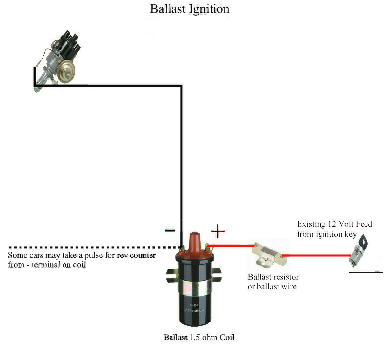
The coil’s low-tension component is to be connected to the chassis’ positive. It is also the ground on an ignition wiring diagram. The high-tension part connects the spark plugs to a positive. To prevent noise the coil’s body metal must be connected with the chassis. It is not required for electrical use. The wiring diagram of the ignition will explain how to connect the terminals of either the negative or positive coils. In some instances, you’ll find that an ignition coil that is malfunctioning is easily identified with scans at an auto parts shop.
The black-and-white-striped wire from the harness goes to the negative terminal. The terminal for the negative is served by the black trace attached to the white wire. The black wire is connected to the contactbreaker. If you’re not sure about the connections of both, you can use a paper clip to remove them from the housing of the plug. Make sure you ensure that the terminals have not been bent.
Accessory terminals
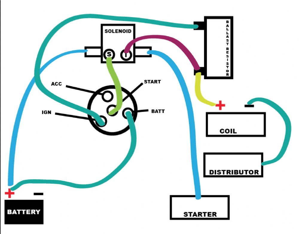
Diagrams of ignition wiring show the wires that are used to power the vehicle’s electrical supply. In general there are four distinct colors-coded terminals that are used for each component. The red color represents accessories, yellow is for the battery and green is for the solenoid for starters. The “IGN” terminal can be used to turn on the car, operate the wipers and other functions. The diagram shows how you can connect the ACC and ST terminals to the rest of the components.
The terminal BAT connects the battery to the charger. The battery is necessary for the electrical system to begin. Furthermore, the switch won’t begin to turn on. It is possible to refer to your wiring diagram if you’re unsure where your car’s batteries are located. The accessory terminals of your vehicle are connected to the battery as well as the ignition button. The BAT terminal is connected to the battery.
Certain ignition switches have an additional position in which users can alter their outputs and control them without having to turn on the ignition. Sometimes, customers may wish to use the auxiliary output separately from the ignition. Make use of the secondary output by connecting the connector to the ACC terminal on the switch with the same colors. While this is a convenient option, there’s an crucial distinction. Most ignition switches are set to have an ACC position when the car is in the ACC position, but they’re set to the START position when the car is in the IGN position.
Gallery of 12v Ignition Coil Ballast Resistor Wiring Diagram
Gallery of 12v Ignition Coil Ballast Resistor Wiring Diagram


