19.5 Horsepower Briggs And Stratton Ignition Switch Wiring Diagram – Let’s start by looking at the various types of terminals in an ignition switch. These include the terminals for the Ignition switch, Coil, and Accessory. After we’ve identified what these terminals are, we will be able to identify the various parts of the ignition wiring. We will also talk about the functions and the Coil. We will then discuss the roles of the Ignition switch as well as Coil.
Terminals for ignition switch
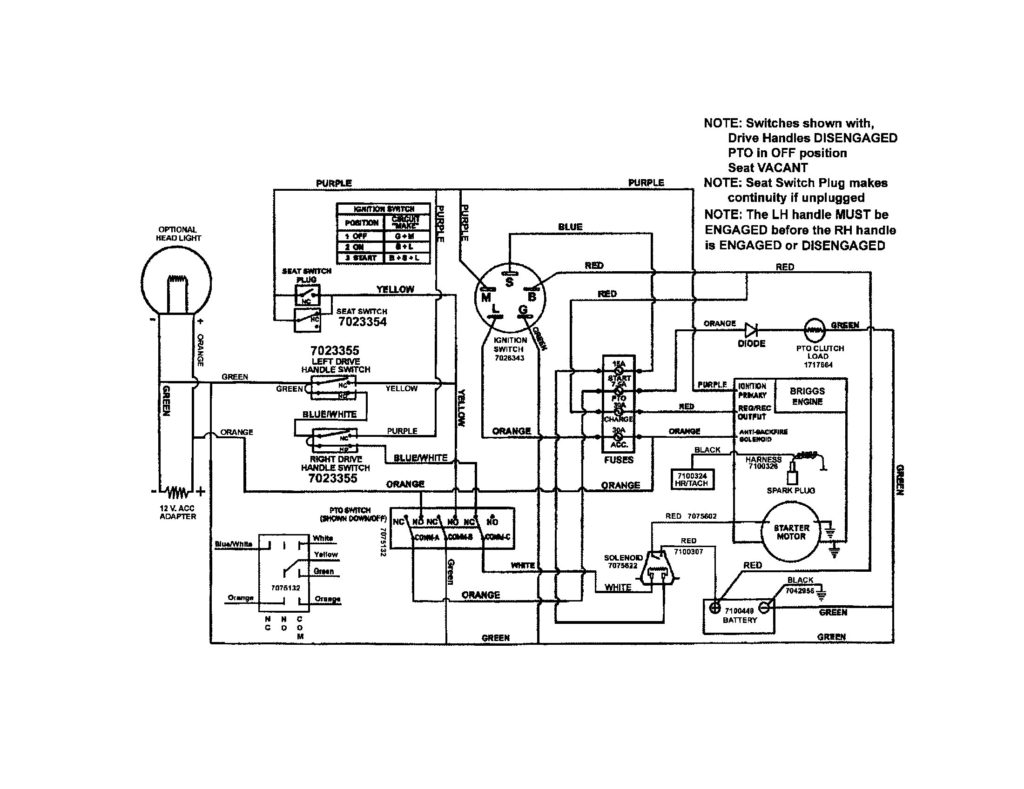
Three switches can be found on the ignition switch. Each of these three switches is able to feed the battery’s voltage to various locations. The first switch is the one that supplies power to the choke, while the second toggles the ON/OFF state of the switch. Different manufacturers use their own color-coding systems for the various conductors, which is documented in another article. OMC uses this method. Connectors can be attached to the ignition switch in order to add the digital Tachometer.
While the majority of ignition switch terminals don’t have an initial number, they could have a different number. To make sure that your wires are plugged in to the switch you must verify their continuity. A cheap multimeter can help you do this. When you’re satisfied with the continuity of your wires, you will be able to install the new connector. The wiring loom of an ignition system switch that is supplied by the manufacturer is distinct.
Understanding how the ACC outputs connect to the auxiliary outputs inside your vehicle is crucial. The ACC and IGN connectors are the standard connections for the ignition switch. Although the START, IGN, and ACC terminals are primary connections to the radio or stereo, the START/IGN terminals are the most important ones. The ignition switch turns the car’s engine on and off. The terminals of the ignition switch on older cars are labeled with the alphabets “ACC” as well as “ST” (for the individual magneto wires).
Terminals for coil
To figure out the type of ignition coil, the first step is to understand the terminology. A simple diagram of the wiring will show a variety of terminals and connections including two primary and two secondary. The coils are equipped with a particular operating voltage, and the first step to determine which one you’ve got is to check the voltage at S1, the primary terminal. S1 should also be checked for resistance to determine if the coil is a Type B, B, or an A coil.
The low-tension coil side must be connected at the chassis’ less. This is the ground on the diagram of ignition wiring. The high-tension side is a positive connection to the sparkplugs. To prevent noise the body of the coil must be connected to chassis. It is not required to connect electrically. The wiring diagram will also illustrate the connection between the positive and negative coils. It is possible to find an issue with the ignition coil that can be easily diagnosed by scanning it in an auto parts store.
The black-and-white-striped wire from the harness goes to the negative terminal. The other white wire has a black trace, and it connects to the positive terminal. The black wire goes to the contact breaker. You can take the black wire from the plug housing with a paper clip If you’re unsure of the connections. Make sure you don’t bend the connectors.
Accessory terminals
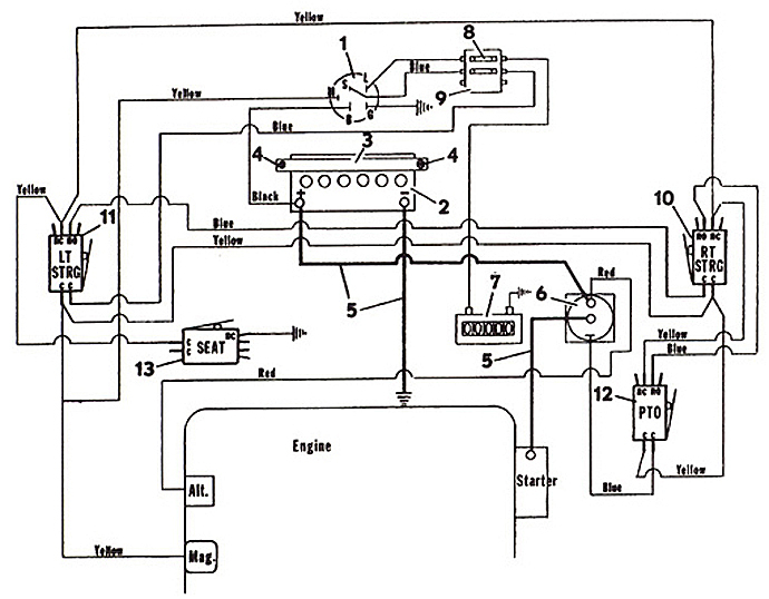
The ignition wiring diagrams show the various wires that are used to power the different components. Each part has four distinct colored connections. Accessories are red while the battery is yellow and the starter solenoid green. The “IGN” terminal can be utilized to turn on the car, turn on the wipers, and other functions. The diagram shows the connections between the ACCand ST terminals.
The terminal known as BAT is where the battery is connected. The electrical system won’t start if the battery isn’t connected. The switch also won’t turn on without the battery. If you’re not sure of where your car’s battery is situated, examine your wiring diagram to see the best way to find it. The accessory terminals in your vehicle are connected to the battery as well as the ignition button. The BAT terminal connects to the battery.
Some ignition switches come with an accessory position. It allows users to access their outputs from a different location without the ignition. Some customers may prefer to utilize the auxiliary output separately from the ignition. To use the additional output, wire the connector with the same colors as ignition, connecting it to the ACC terminal on the switch. While this is an excellent feature, there is one crucial distinction. Many ignition switches have an ACC position when your car is in the ACC mode and a START position when you are in IGN.
Gallery of 19.5 Horsepower Briggs And Stratton Ignition Switch Wiring Diagram
Gallery of 19.5 Horsepower Briggs And Stratton Ignition Switch Wiring Diagram


