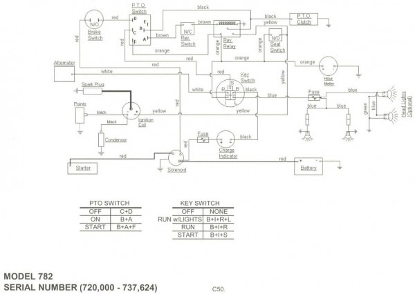
1948 Farmall Cub Ignition Switch Wiring Diagram Picture – Let’s start by looking at the various kinds of terminals that are found in an ignition switch. These terminals are for the Ignition button, Coil and Accessory. After we’ve established what these types of terminals are for, we will proceed to discover the various components of the 1948 Farmall Cub Ignition Switch Wiring Diagram Picture. Then, we will discuss the roles of the Ignition switch as well as the Coil. After that we will move on to the Accessory Terminals.
Terminals for ignition switches
There are three switches in the ignition switch, and they provide the battery’s voltage to several different locations. The first one is used to drive the choke through pushing it. Then, the third switch is used to control the ON/OFF position. Different manufacturers use different color-coding methods to identify different conductors. We will cover this in another article. OMC follows the same system. The ignition switch also includes an adapter for the addition of the Tachometer.
Although the majority of ignition switch terminals aren’t original, the numbering for each one may not be in line with the diagram. Verify the integrity of the wires first to make sure they’re properly connected to the ignition switch. A cheap multimeter can assist you in this. Once you are happy with the continuity of the wires, you can install the new connector. The wiring loom used in a factory-supplied ignition system switch is distinct.
It is essential to know how the ACC outputs and the auxiliary outputs function in order to connect them. The ACC and IGN connectors are the default connections for the ignition switch. Although the START, IGN, and ACC terminals are primary connections for the radio or stereo, the START/IGN connections are the main ones. The ignition switch switches the car’s engine ON and OFF. Older cars have the ignition switch terminals marked “ACC” or “ST” (for individual magnetowires).
Terminals for coil
Understanding the terminology is the initial step towards knowing what type of ignition coil you’ve got. A basic ignition wiring layout will provide you with a range of connections and terminals. It is essential to identify the kind of coil you are using by testing the voltage on the primary terminal, called S1. S1 must also go through resistance tests to determine if it are an A or B coil.
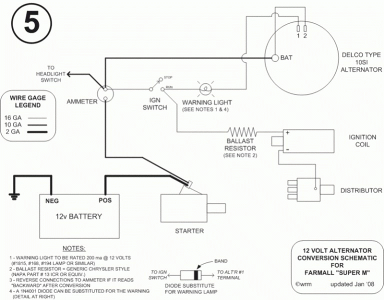
The low-tension side of the coil needs to be connected to the chassis’ negative. This is the ground in the ignition wiring diagram. The high-tension side supplies the positive power directly to the spark plugs. The body of the coil has to be connected to the chassis to suppress the effect however it isn’t electrically necessary. The ignition wiring diagram will also indicate how to connect the positive coil terminals. In some cases, you’ll find that an ignition coil that is malfunctioning is identified by scans in an auto parts store.
The black-and-white-striped wire from the harness goes to the negative terminal. The terminal that is negative is served by the black trace that’s joined to the white wire. The black wire connects to the contact breaker. If you’re not certain about the connection between the twowires, use an old paper clip to take them from the housing of the plug. It’s also crucial to ensure that the terminals don’t bend.
Accessory terminals
The diagrams for ignition wiring show the wiring used in the vehicle’s power supply. There are generally four colored terminals that correspond to each component. Red refers to accessories, yellow is the battery, and green for the starter solenoid. The “IGN” terminal can be used to turn on the car, operate the wipers and other features. The diagram illustrates how you can connect ACC or ST terminals and the rest.
The terminal BAT holds the battery. The electrical system is not able to begin without the battery. Also, the switch won’t be able to turn on without the battery. It is possible to look up your wiring diagram to determine where your car’s batteries are located. The accessory terminals in your vehicle are connected to the battery and the ignition switch. The BAT Terminal is connected to the Battery.
Certain ignition switches have a separate “accessory” location, which allows users can control their outputs without using the ignition. Customers sometimes want an auxiliary output that can be used independently from the ignition. Make use of the additional output by connecting the connector to the ACC terminal on the switch with the same colors. This convenience feature is great however there’s a distinction. Some ignition switches are set to have an ACC location when the car is in the ACC position. They will also be in the START mode once the vehicle is entered the IGN position.
Gallery of 1948 Farmall Cub Ignition Switch Wiring Diagram Picture
Gallery of 1948 Farmall Cub Ignition Switch Wiring Diagram Picture


