1956 Chevy Bel Air Ignition Switch Wiring Diagram – We will first examine the different types of terminals that are used on the ignition switch. These are the terminals for the Ignition, Coil, or Accessory. Once we know what these types of terminals are for We will then determine the various parts of the 1956 Chevy Bel Air Ignition Switch Wiring Diagram. In addition, we will discuss the functions of the Ignition switch and Coil. Then, we’ll turn our attention to the Accessory terminals.
The terminals of the ignition switch
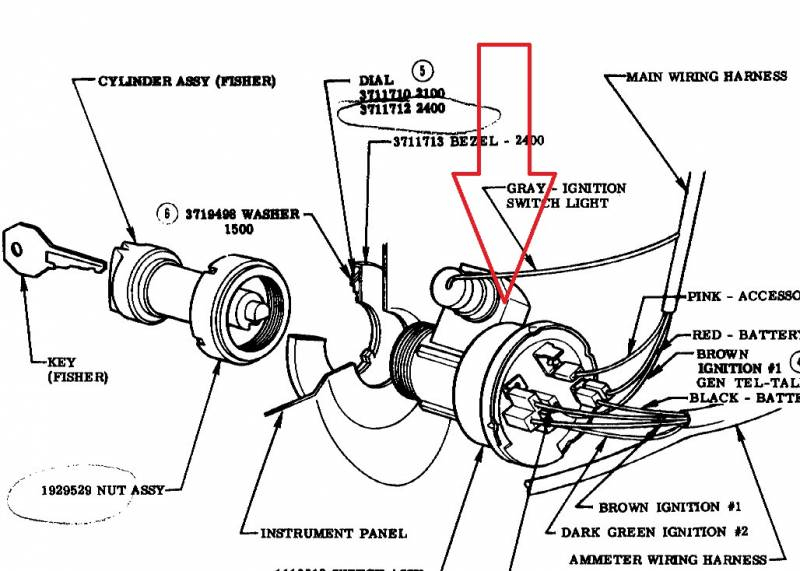
The ignition switch has three switches. They feed the voltage of the battery to many different locations. The first switch powers the choke. The third switch regulates the ON/OFF function of the ignition switch. Every manufacturer has its own color-coding system, which we will discuss in another article. OMC utilizes this method. The ignition switch also includes a connector for adding a tachometer.
Although the majority of ignition switch terminals don’t have an initial number, they could have a different one. To make sure that your wires are properly connected to the ignition switch, it is recommended to check their continuity. This can be accomplished with a multimeter that is inexpensive. Once you’re satisfied with the connection then you can connect the new connector. The wiring loom used in a factory-supplied ignition system switch is different.
It is important to understand how the ACC outputs and the auxiliary outputs function to connect them. The ACC/IGN connections function as the default connections for the ignition switch. The START/IGN connections connect to the stereo or radio. The ignition switch’s function is to turn the engine of your car on and off. The terminals on older cars ignition switches are marked with “ACC” and ST (for the individual magneto wires).
Terminals for coil
Understanding the terms is the initial step towards determining which type of ignition coil you own. You will see several connections and terminals within the basic wiring diagram for ignition which includes two primary and two secondary. Each coil is operating at a certain voltage. The first step to determine the type you’re using is to examine the voltage of S1 or the primary terminal. S1 must be tested for resistance in order to identify if the coil is Type A, B, and/or C.
The coil with low tension must be connected at the chassis’s plus. This is what is known as the ground for the ignition wiring. The high-tension end supplies positive direct to the sparkplugs. For suppression purposes the body of the coil must be connected to chassis. It is not necessary to electrically connect. The ignition wiring diagram will also show how to connect the positive coil terminals. In certain instances scanning the local auto parts store can help you identify malfunctioning ignition coils.
The black-and-white-striped wire from the harness goes to the negative terminal. Positive terminal receives a second white wire, which includes a black trace. The black wire connects to the contact breaker. To verify the connections, you can employ a paperclip, or a pencil to lift them out of the plug housing. Make sure that the connectors don’t bend.
Accessory terminals
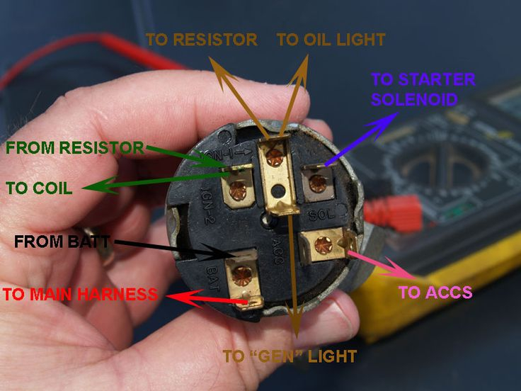
The ignition wiring diagrams illustrate the various wires used to power the car’s various components. There are generally four color-coded terminals that correspond to each component. The red color is used for accessories and yellow is for the battery, while green is for the solenoid for starters. The “IGN terminal is used to start the car, operating the wipers and various other functions. This diagram shows how you can connect ACC and ST terminals to the other components.
The battery is connected to the terminal called BAT. The electrical system is not able to begin without the battery. Furthermore, the switch won’t start. If you’re not sure the exact location where the battery in your car is situated, you can examine the wiring diagram of your car to determine the best way to find it. The ignition switch is connected to the car’s battery. The BAT Terminal is connected to the Battery.
Some ignition switches come with an independent “accessory” position, in which users can control their outputs with no ignition. Sometimes, customers would like an auxiliary output that can be used separately from the ignition. To use the auxiliary output, connect the connector using the same colors as ignition and connect it to the ACC terminal on the switch. While this is an excellent option, there’s an important difference. Most ignition switches will be in an ACC position when the vehicle is in the ACC however they’ll be in the START position when the vehicle is in IGN.
Gallery of 1956 Chevy Bel Air Ignition Switch Wiring Diagram
Gallery of 1956 Chevy Bel Air Ignition Switch Wiring Diagram


