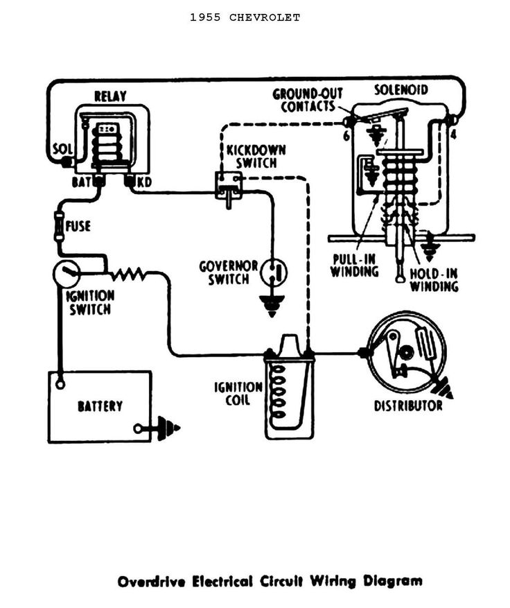
1957 Corvette Ignition Switch Wiring Diagram – First, we will examine the different types of terminals on the ignition switch. These are the terminals that connect the Ignition, Coil, or Accessory. Once we know the terminals used and which ones are not, we can recognize the various parts of the 1957 Corvette Ignition Switch Wiring Diagram. In addition, we will discuss the roles of the Ignition switch, and Coil. Then we’ll move on to the Accessory Terminals.
Terminals for the ignition switch
Three switches can be found in an ignition switch. Each of the three switches is able to feed the battery’s voltage to several different destinations. The first switch provides power to the choke and the third switch toggles the ON/OFF state of the switch. Each manufacturer has their unique color-coding system, which we will discuss in another article. OMC uses this procedure. An adapter is included on the ignition switch to allow for the addition of an Tachometer.
Although the majority of ignition switch terminals do not have an original number, they may have a different number. Check the integrity of the wires to determine if they’re plugged into the correct ignition switch. You can do this with a simple multimeter. When you are satisfied with the continuity of the wires, connect the new connector. If you’re using a factory-supplied ignition switch, the wiring loom is different from that you have in your car.
Before connecting the ACC outputs to the auxiliary outputs of your car it is crucial to know the fundamentals of these connections. The ACC/IGN terminals function as the default connection on the ignition switch. The START/IGN terminals connect to the radio or stereo. The ignition switch is the one that controls the engine of your car. The ignition switch terminals on older cars are identified with the initials “ACC” and “ST” (for the individual magneto wires).
Terminals for coil
The terms used to define the model and type of the ignition coil is the first thing. The diagram of the basic ignition wiring illustrates a variety of connections and terminals. There are two primary and secondary connections. You must determine the kind of coil you own by examining the voltage at the primary terminal, called S1. S1 should also be tested for resistance to determine whether it’s an A, Type B or A coil.
The low-tension coil side must be connected at the chassis’s minus. This is also the ground in the ignition wiring diagram. The high-tension end provides positive direct to the sparkplugs. It is necessary for suppression purposes that the body of the coil’s metal be connected to its chassis but not essential. The ignition wiring diagram will also outline the connection of the positive coil terminals. In some cases, you’ll find that the ignition coil is damaged and can be diagnosed with scanning in an auto parts store.
The black-and-white-striped wire from the harness goes to the negative terminal. The positive terminal is connected to the white wire with a trace of black. The black wire connects to the contactbreaker. If you’re not certain about the connection between the two, try using a paper clip to remove them from the plug housing. Make sure you ensure that the terminals have not been bent.
Accessory terminals
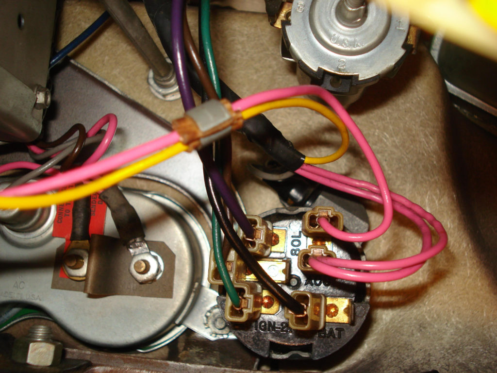
The diagrams for ignition wiring illustrate the wires that are used in the power supply of the vehicle. Typically there are four colors-coded terminals that are used for each component. Red is used to indicate accessories, yellow to the battery and green for the starter solenoid. The “IGN” terminal is used for starting the car, operating the wipers and other functions. This diagram shows how to connect ACC and ST terminals with the rest of components.
The terminal called BAT is the location where the battery is. The electrical system can’t begin without the battery. A dead battery could cause the switch to not turn on. It is possible to look up your wiring diagram to figure out the location of your car’s batteries. placed. The accessory terminals of your car are connected to the battery as well as the ignition button. The BAT connector connects to your battery.
Some ignition switches are equipped with an accessory position. This allows users to access their outputs from another location without the ignition. Users may wish to utilize the auxiliary output independently of the ignition. You can use the auxiliary output by connecting it to an ACC terminal on your switch with the same colors. This convenience feature is great however there’s a distinction. The majority of ignition switches are set to be in an ACC position when the car is in the ACC position, whereas they’re in the START position when the car is in the IGN position.
Gallery of 1957 Corvette Ignition Switch Wiring Diagram
Gallery of 1957 Corvette Ignition Switch Wiring Diagram


