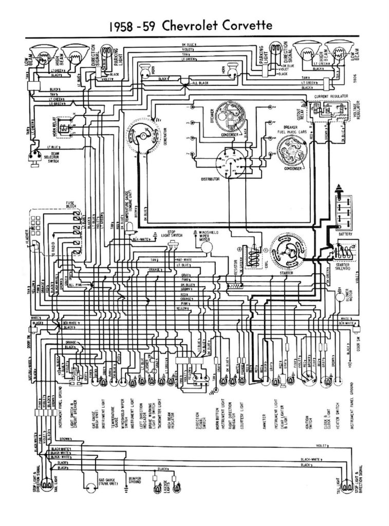
1958 Chevy Truck Ignition Switch Wiring Diagram – First, we will examine the different types of terminals that are used on the ignition switch. These terminals are used for the Ignition button, Coil and Accessory. After we’ve identified what these terminals are, we will be able to identify the various parts of the ignition wiring. We’ll also go over the functions of the Ignition switch and Coil. Following that, we will proceed to the Accessory Terminals.
Terminals for the ignition switch
An ignition switch has three switches that supply the battery’s current to various locations. The first switch powers the choke. The second switch controls the ON/OFF of the ignition switch. Different manufacturers use various color codes for the various conductors. This is explained in another article. OMC utilizes the same system. A connector is also included in the ignition switch for connecting an Tachometer.
While the majority of the ignition switch terminals may not be original, the numbers for each may not match the diagram. Check the continuity of all wires to ensure that they are properly connected to the ignition switches. A multimeter is a great tool to check the continuity. After you’re satisfied with the integrity of the wires, connect the new connector. If your vehicle is equipped with an installed ignition switch, the wiring diagram will differ.
Understanding how the ACC outputs are connected to the auxiliary outputs in your car is essential. The ACC, IGN and START terminals are the default connection to the ignition switch. They are also the main connections to the radio and stereo. The ignition switch regulates the engine in your car. On older vehicles the ignition switch’s terminals are identified with the initials “ACC” and “ST” (for individual magnet wires).
Terminals for coil
The first step in determining the type of ignition coil is to know the terminology used. A basic diagram of the wiring will show you a number of terminals and connections. The operating voltage of every coil is different. This is why it is important to first test the voltage at the S1 (primary terminal). S1 should be tested for resistance in order to identify if the coil is Type A, B, or C.
The coil’s low-tension end must be connected to the chassis’ positive. This is the ground on the wiring diagram for ignition. The high-tension side is a positive connection to the sparkplugs. The aluminum body of the coil has to be connected to the chassis for suppression, but it isn’t electrically required. The wiring diagram will also illustrate the connection between the positive and negative coils. Sometimes, a check at an auto parts shop can detect a defective ignition wire.
The black-and-white-striped wire from the harness goes to the negative terminal. The white wire is the other one. It has a black trace on it, and it connects to the positive terminal. The black wire connects with the contact breaker. You can remove the black wire from the plug housing with a paper clip in case you are uncertain about the connections. It is also important to make sure the terminals do not bend.
Accessory terminals
Diagrams of ignition wiring show the wires that supply power to different parts of the vehicle. Each component has four distinct connections that are color coded. Red is used for accessories, yellow is for the battery, and green is the starter solenoid. The “IGN terminal” is used to run the wipers, as well as other operating features. This diagram shows how to connect ACC and ST terminals to the rest of the components.
The terminal referred to as BAT is the place where the battery is. The electrical system cannot begin without the battery. In addition, the switch will not begin to turn on. The wiring diagram will tell you where to find your car’s battery. The ignition switch is connected to the car’s battery. The BAT terminal is connected to the battery.
Some ignition switches come with an accessory position. This allows users to connect their outputs to a different location without the ignition. Sometimes, customers wish to utilize the auxiliary output separately from the ignition. You can use the additional input by connecting the connector to the ACC terminal. This is a great feature, but there is one important difference. Many ignition switches have an ACC position when your car is in the ACC mode, and a START position when the switch is in IGN.
Gallery of 1958 Chevy Truck Ignition Switch Wiring Diagram
Gallery of 1958 Chevy Truck Ignition Switch Wiring Diagram


