1963 Lincoln Continental Ignition Switch Wiring Diagram – Let’s first examine the various terminals used on the ignition switch. They include terminals for Coil, Ignition Switch, and Accessory. Once we know the terminals that are utilized, we can begin to recognize the various parts of the 1963 Lincoln Continental Ignition Switch Wiring Diagram. In addition, we will discuss the roles of the Ignition switch and Coil. We will then discuss the function of the ignition switch and Coil.
Terminals for ignition switches
Three switches are found in an ignition switch. Each of these three switches feeds the battery’s voltage to a variety of destinations. The ON/OFF position of the ignition switch is controlled by the third switch, which provides power to the choke whenever it’s pulled. Different manufacturers have different color-coding systems for different conductors. This will be covered in a different article. OMC utilizes this procedure. The connector allows for the attachment of a speedometer the ignition switch.
While most ignition switch terminals are duplicated, the numbers may not match the diagram. Before plugging into the ignition switch, make sure to check the continuity. A multimeter is an excellent tool to test the continuity. After you have verified that the wires are in good condition, you can connect the connector. The wiring loom for an ignition switch that’s factory-supplied will be different than the one that you have in your car.
In order to connect the ACC outputs to the auxiliary outputs on your car, you’ll need to understand the way these two connections function. The ACC and IGN connectors are the standard connections for your ignition switch. Although the START, IGN, and ACC terminals are primary connections for radios or stereo, the START/IGN terminals are the most important ones. The ignition switch switches the car’s engine on and OFF. In older vehicles, the ignition switch terminals are identified with the initials “ACC” and “ST” (for the individual magnetic wires).
Terminals for coil
To determine the type of ignition coil you need to know the step is to understand the terms. The basic ignition wiring diagram illustrates a variety of connections and terminals. There are two primary and one secondary. It is essential to identify the type of coil you own by examining the voltage at the primary terminal, S1. S1 must also be subjected to resistance tests to determine if it are an A or B coil.
The negative end of the chassis end should be connected to the coil’s low-tension end. This is exactly what you can see on the diagram of wiring. The high-tension supply provides positive directly to spark plugs. The aluminum body of the coil has to be linked to the chassis to prevent it from being smothered, but it isn’t electrically required. You will also see the connections between the negative and positive coil’s terminals on the diagram of the ignition wiring. In certain instances, you’ll find that the ignition coil is damaged and is identified by scans in an auto parts store.
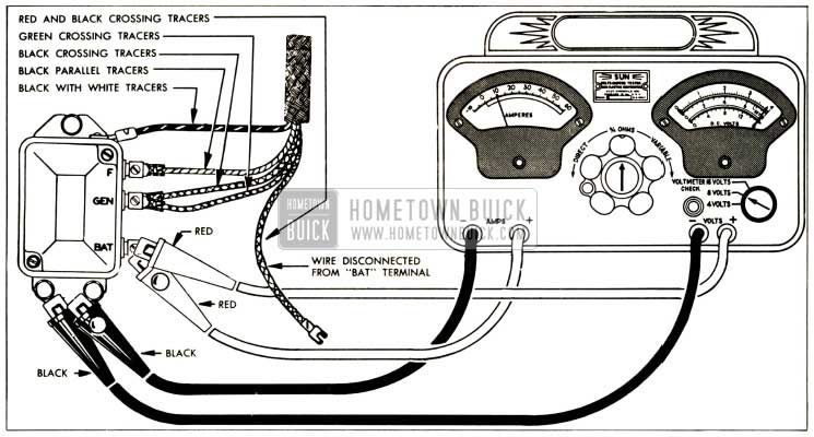
The black-and-white-striped wire from the harness goes to the negative terminal. The white wire is the other one. It is black with a trace on it, and it connects to the positive terminal. The black wire connects to the contact breaker. To verify the wires’ connections, use a paperclip and remove them from the housing. Make sure you verify that the connections have not been bent.
Accessory Terminals
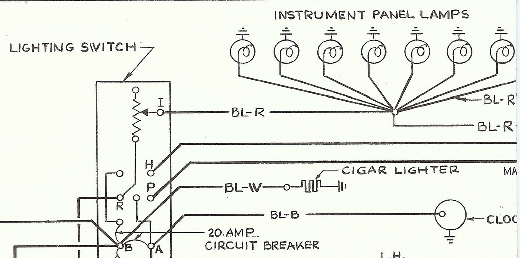
The wiring diagrams of the ignition illustrate the various wires that provide power to the various parts of the vehicle. There are usually four different colored terminals for each component. The accessories are red while the battery is yellow the starter solenoid is green. The “IGN” terminal can be used to start the car, turn on the wipers, as well as other features. The diagram below shows how to connect the ACC terminal as well as the ST terminals to various components.
The battery is attached to the terminal called BAT. Without the battery, the electrical system does not begin. The switch won’t turn on if the battery isn’t there. It is possible to view your wiring diagram to determine where the batteries of your car are placed. The ignition switch as well as the battery are connected via accessory terminals. The BAT terminal is connected to the battery.
Some ignition switches are equipped with an additional position. This allows users to access their outputs from another location without the ignition. Sometimes, a customer wants to utilize an auxiliary output that is separate from the ignition. In order for the auxiliary output be used, connect the connector with the same shade as that of the ignition. Connect it to the ACC end of the switch. While this is an excellent feature, there is one important difference. Most ignition switches are designed to display an ACC status when the vehicle is at either the ACC or START positions.
Gallery of 1963 Lincoln Continental Ignition Switch Wiring Diagram
Gallery of 1963 Lincoln Continental Ignition Switch Wiring Diagram


