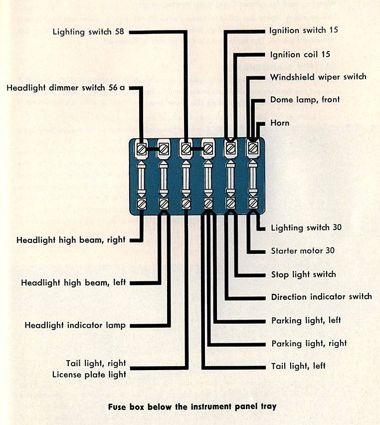
1963 Mercury Ignition Wiring Diagram – The first step is to look at the different terminals that are used in the ignition switch. The terminals are the Ignition switch, the Coil and the Accessory. After we’ve identified the purpose of the terminals it is possible to recognize the various parts of the ignition wiring. We’ll also go over the functions for the Ignition switch, as well as the Coil. Then, we’ll focus on the accessory terminals.
Terminals for the ignition switch
There are three separate switches on an ignition switch, which feed the battery’s voltage to several different destinations. The first switch provides the choke with power when it is pushed. The second is the ignition switch’s ON/OFF position. Different manufacturers have different color codes for different conductors. This is described in a different article. OMC uses this method. The adapter is attached to the ignition switch, allowing the installation of the Tachometer.
While most ignition switch terminals can be duplicated, the numbers may not be consistent with the diagram. Check the electrical continuity to see if they are connected to the ignition switch correctly. A multimeter is an excellent tool to test the continuity. When you are satisfied with the continuity of the wires connect the new connector. The wiring loom of the ignition switch supplied by the factory will be different from the one that you have in your car.
Understanding how ACC outputs are connected to the other outputs of your vehicle is crucial. The ACC and IGN connectors are the default connections for your ignition switch. While the START, IGN, and ACC terminals are the primary connections for radios or stereo, the START/IGN connections are the primary ones. The ignition switch is responsible for turning the engine of your car to and off. The terminals of older vehicles ignition switches are identified by “ACC” as well as ST (for the individual magneto wires).
Coil terminals
Understanding the terms is the initial step towards finding out what kind of ignition coil you have. In a basic ignition wiring diagram you’ll see a number of different terminals and connections, including two primary and two secondary. Each coil is equipped with a distinct operating voltage. To determine the type of coil you have the first step is to check the voltage at S1, the primary terminal. S1 should also be checked for resistance to determine whether it’s an A, Type B or an A coil.
The negative of the chassis must be connected to the low-tension side. This is what you find in the diagram of wiring. The high-tension supply provides positive directly to spark plugs. To reduce the noise, the coil’s metal body is required to be connected to the chassis. But, it’s not required to connect electrically. You will also see the connections of the positive and negative coil terminals on the ignition wiring diagram. Sometimes, an inspection at an auto parts store could diagnose a malfunctioning ignition wire.
The black-and-white-striped wire from the harness goes to the negative terminal. The white wire is the other one. It is black with a trace, and it connects to the positive terminal. The black wire connects to the contact breaker. If you’re not sure about the connection between the two, try using a paper clip to remove them from the housing of the plug. Make sure you ensure that the terminals have not been bent.
Accessory terminals
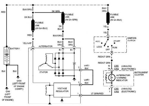
Diagrams of ignition wiring illustrate the wiring used to supply power to different parts of the vehicle. There are usually four different color-coded terminals to each component. The red color is used for accessories and yellow is for the battery, while green is the solenoid for starters. The “IGN” terminal can be utilized to turn on the car, operate the wipers and other functions. The diagram demonstrates how to connect the ACC and ST terminals to the other components.
The terminal referred to as BAT is the place where the battery is. The electrical system can’t be started without the battery. The switch also won’t be able to turn on without the battery. If you’re not sure of the exact location where the battery in your car is situated, look at your wiring diagram to figure out how to locate it. The accessory terminals of your car are connected to the battery as well as the ignition button. The BAT connector is connected to your battery.
Some ignition switches offer the option of an “accessory position” which allows users to alter their outputs without the ignition. Users may wish to utilize the auxiliary output independently of the ignition. To make use of the auxiliary output, connect the connector using the same colors as the ignition connecting it to the ACC terminal on the switch. While this is an excellent option, there’s an significant difference. The majority of ignition switches are designed to display an ACC status when the car’s at the ACC or START positions.
Gallery of 1963 Mercury Ignition Wiring Diagram
Gallery of 1963 Mercury Ignition Wiring Diagram


