1965 F100 Ignition Switch Wiring Diagram – First, let’s take a look at the different types of terminals on the ignition switch. These include the terminals that are for the Ignition switch, Coil, and Accessory. Once we understand the function of each type of terminal, we can then identify the parts of the ignition wiring. We will also talk about the functions as well as the Coil. Then, we will focus on the accessory terminals.
Terminals for ignition switch
The ignition switch is comprised of three different switches that direct the battery’s power to various locations. The first is used to drive the choke by pushing it. Then, the second is for the ON/OFF position. Different manufacturers have their own color-coding system for different conductors that is described in a separate article. OMC utilizes this method. A connector can be added to the ignition switch to include the digital tachometer.
Even though some of the ignition switch terminals might not be original, the numbering of each one might not be in line with the diagram. Examine the continuity of the wires first to ensure they are correctly plugged in the ignition switch. A multimeter is a good tool to check the continuity. Once you’re satisfied with the quality of the connection then you can connect the new connector. If your vehicle is equipped with an installed ignition switch the wiring diagram may differ.
The first step is to understand the distinctions between the ACC and auxiliary outputs. The ACC/IGN connections function as the default connection on the ignition switch. The START/IGN terminals connect to the stereo or radio. The ignition switch acts as the engine’s on/off button. On older vehicles, the ignition switch terminals are identified with the alphabets “ACC” and “ST” (for individual magnet wires).
Terminals for Coil
To identify the kind of ignition coil you need to know the step is to learn the terminology. In a simple diagram of the wiring for ignition there are a number of different connections and terminals, such as two primary and two secondary. The operating voltage of each coil is different. Therefore, it is crucial to test the voltage at the S1 (primary terminal). Also, you should examine S1 for resistance in order to determine if it’s an A, B, or C coil.
The lower-tension side of the coil should be connected to the chassis the negative. This is what is known as the ground for the ignition wiring. The high tension side provides positive directly the spark plugs. For suppression purposes the coil’s body metal is required to be connected to the chassis. It is not required for electrical use. The diagram of the ignition wiring will also show how to connect the positive coil’s terminals. In some instances it is possible to find an ignition coil that is malfunctioning is easily identified with scans in an auto parts store.
The black-and-white-striped wire from the harness goes to the negative terminal. The positive terminal also receives the white wire that includes a black trace. The black wire is connected to the contactbreaker. If you’re not sure about the connection between the twowires, use a paper clip to remove them from the plug housing. It is also important to ensure that the terminals aren’t bent.
Accessory terminals
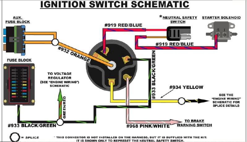
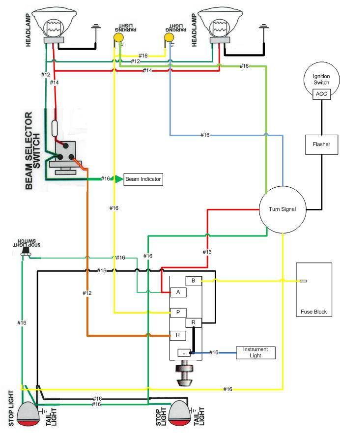
The ignition wiring diagrams illustrate the various wires utilized to power the vehicle’s various parts. There are usually four color-coded terminus for each component. The red symbol represents accessories, yellow is for the battery, and green for the solenoid for starters. The “IGN” terminal is used for starting the car, controlling the wipers, and for other functions. This diagram shows how you can connect ACC and ST terminals with the rest of the components.
The terminal BAT holds the battery. Without the battery the electrical system can not begin. The switch won’t be able to turn on if there is no battery present. If you’re not sure the exact location where the battery in your car is situated, you can look at the wiring diagram of your car to determine how to locate it. The ignition switch and battery are connected through the accessory terminals. The BAT terminal is connected to the battery.
Some ignition switches offer an additional “accessory position” which allows users to adjust their outputs independently of the ignition. Sometimes, customers wish to make use of an auxiliary output that is separate from the ignition. The auxiliary output is utilized by wiring the connector with the same color as your ignition and connecting it to the ACC terminal of the switch. This is a useful feature, however there’s an important distinction. Most ignition switches will be in an ACC position when the vehicle is in the ACC however they’ll be in the START position when the vehicle is IGN.
Gallery of 1965 F100 Ignition Switch Wiring Diagram
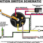
Gallery of 1965 F100 Ignition Switch Wiring Diagram


