1965 Pontiac Gto Ignition Switch Wiring Diagram – The first step is to take a look at the different kinds of terminals for the ignition switch. These are terminals for the Ignition, Coil, or Accessory. When we have a clear understanding of the purpose of each terminal, it is possible to identify the parts of the ignition wiring. We’ll also discuss the functions as well as the Coil. Next, we’ll discuss the function of the Ignition switch and Coil.
Terminals for the ignition switch
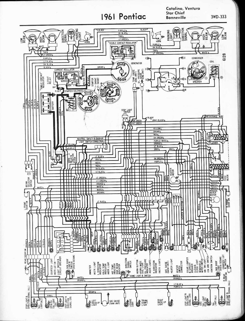
The ignition switch is comprised of three switches that supply the battery’s current to various locations. The first switch is utilized to drive the choke by pushing it. Then, the second is for the ON/OFF position. Each manufacturer has its individual color-coding system that we’ll go over in a separate article. OMC uses this system. The ignition switch also includes an adapter for the addition of an tachometer.
While many ignition switch terminals might not be authentic, the numbering of the terminals may not be in line with the diagram. Examine the continuity of the wires first to make sure they’re connected correctly to the ignition switch. This can be done using a simple multimeter. After you’ve confirmed that the wires are in good condition, you can connect the connector. If your car has an installed ignition switch the wiring diagram will differ.
It is important to understand how the ACC outputs and auxiliary outputs function to join them. The ACC, IGN and START terminals are the default connections to the ignition switch. They are also the primary connections to your radio and stereo. The ignition switch operates the engine’s switch to turn off or on. On older vehicles the terminals of the ignition switch are identified with the alphabets “ACC” and “ST” (for distinct magnetic wires).
Terminals for coil
To determine the type of ignition coil you need to know the step is to know the terms. An ignition wiring diagram will display a range of terminals and connections, including two primary and two secondaries. The voltage that operates on each coil is different. This is why it is important to first test the voltage at the S1 (primary terminal). It is also recommended to examine S1 for resistance in order to determine if it’s a Type A B, C, or coil.
The coil’s low-tension end is to be connected to the chassis’ positive. This is the ground in the ignition wiring diagram. The high tension part supplies positively directly to the spark plugs. The metal body of the coil needs to connect to the chassis for suppression purposes but is not electrically essential. The ignition wiring diagram will also show you the connections between the positive and negative coil’s terminals. Sometimes, a defective ignition coil can be identified with a scan at an auto parts shop.
The black-and-white-striped wire from the harness goes to the negative terminal. The positive terminal also receives a white wire that has a black trace. The black wire is connected to the contactbreaker. To confirm the connections, you can use a paperclip or a pencil to pull them out of the plug housing. Be sure that you don’t bend the connectors.
Accessory terminals
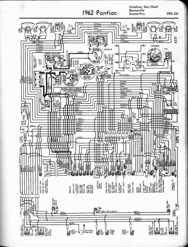
Diagrams of the ignition wiring illustrate the wiring used to power various parts of the vehicle. Typically there are four distinct colors-coded terminals that are used for each component. Red is used for accessories and yellow is for the battery, and green is for the solenoid for starters. The “IGN terminal” is used to power the wipers as well as other operating functions. The diagram shows the connection of the ACCas well as ST terminals.
The terminal BAT holds the battery. The battery is essential to allow the electrical system to get started. Additionally, the switch won’t begin to turn on. The wiring diagram will show you the location of your car’s battery. The accessory terminals of your car connect to the ignition switch and the battery. The BAT connector is connected to your battery.
Some ignition switches are equipped with an additional position. This allows users to connect their outputs to a different place without having to turn on the ignition. Some customers prefer to utilize an additional output that is not connected to the ignition. You can utilize the secondary input by connecting the connector to the ACC terminal. While this is an excellent feature, there’s one significant difference. Most ignition switches will be in an ACC position when the vehicle is in the ACC however they will be in the START position when the car is in IGN.
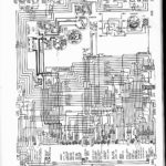
Gallery of 1965 Pontiac Gto Ignition Switch Wiring Diagram
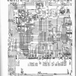
Gallery of 1965 Pontiac Gto Ignition Switch Wiring Diagram


