1968 Chevy C10 Ignition Switch Wiring Diagram – We will first take a look at the various kinds of terminals found in the ignition switch. These terminals comprise the Ignition switch as well as the Coil and the Accessory. After we’ve identified what these terminals do and what they do, we can then be able to identify the various parts of the ignition wiring. We will also cover the functions of both the Ignition Switch and the Coil. Then, we will concentrate on the accessory terminals.
The ignition switch’s terminals
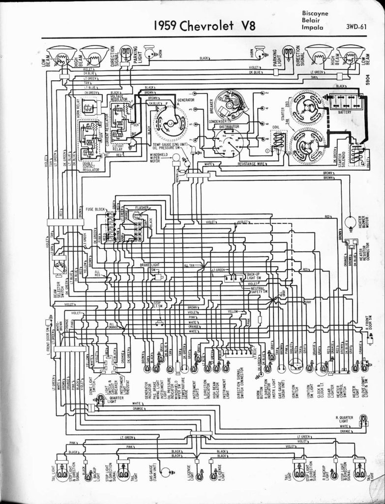
An ignition switch is comprised of three switches. They transmit the battery’s voltage to different places. The first one is used to power the choke by pushing it. Then, the second is for the ON/OFF position. Different manufacturers use different colors-coding systems to match the conductors. OMC uses the same method. The ignition switch also includes a connector for adding the timer.
While many ignition switch terminals could not be original, the numbers of the terminals may not be in line with the diagram. To make sure that the wires are plugged in to the switch you should check their continuity. You can do this with a simple multimeter. When you are happy with the continuity of the wires you can connect the new connector. If you have an ignition switch that is supplied by the manufacturer the wiring loom will be different from that used in your vehicle.
It is important to understand the ways in which the ACC outputs and the auxiliary outputs function in order to connect them. The ACC/IGN terminals act as the default connection on the ignition switch. The START/IGN connections connect to the stereo or radio. The ignition switch is the one that turns the car’s engine on and off. Older vehicles have ignition switch’s terminals that are labeled “ACC” or “ST” (for individual magnetowires).
Terminals for Coil
The terminology used to determine the kind and model of the ignition coil is the primary thing. You will see several connections and terminals on the basic wiring diagram for ignition, including two primary, and two secondary. You must determine the kind of coil you are using by testing the voltage at the primary terminal, S1. S1 must also be subjected to resistance tests to determine if it’s a Type A or B coil.
The lower-tension side of the coil must be connected to the chassis”negative. This is what is known as the ground for the wiring for ignition. The high-tension end supplies positive direct to the sparkplugs. The coil’s aluminum body needs to be connected to the chassis to prevent it from being smothered but isn’t required. The diagram of the ignition wiring will also outline the connection of the positive coil’s terminals. In certain instances, you’ll find that the ignition coil is damaged and is identified by scans in an auto parts store.
The black-and-white-striped wire from the harness goes to the negative terminal. The terminal that is negative is served by the trace in black that’s joined to the white wire. The black wire connects to the contactbreaker. If you’re not sure about the connections between the two, try using the clip of a paperclip to remove them from the housing of the plug. It’s also essential to make sure that the terminals don’t bend.
Accessory terminals
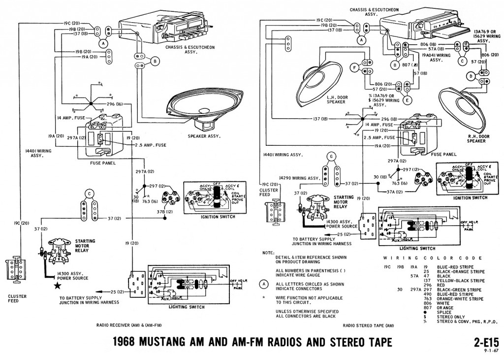
The wiring diagrams for the ignition show the different wires that provide power to the various parts of the vehicle. There are typically four colored terminals that correspond to the respective component. The red symbol represents accessories, yellow represents the battery and green for the starter solenoid. The “IGN terminal lets you start the car, control the wipers or other features that operate. The diagram illustrates how to connect ACC or ST terminals and the rest.
The terminal BAT holds the battery. Without the battery the electrical system can not begin. A dead battery can cause the switch to not come on. It is possible to view the wiring diagram of your car to see the location of your car’s batteries. situated. The ignition switch and the battery are connected via accessory terminals. The BAT terminal is connected to the battery.
Certain ignition switches come with an accessory setting where users can adjust their outputs and manage them without needing to use the ignition. In some cases, users may want to use the auxiliary input independently of the ignition. In order for the auxiliary output be used, connect the connector with the same color as that of the ignition. Connect it to the ACC end of the switch. This is a useful feature, but there is one important distinction. The majority of ignition switches are configured to show an ACC status when the car is in either the ACC or START positions.
Gallery of 1968 Chevy C10 Ignition Switch Wiring Diagram
Gallery of 1968 Chevy C10 Ignition Switch Wiring Diagram


