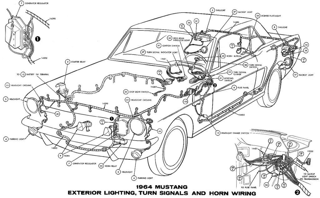
1968 Ford Mustang Ignition Switch Wiring Diagram – We will first look at the various types of terminals on the ignition switch. These include the terminals that are for the Ignition switch, Coil, and Accessory. Once we know the terminals used and which ones are not, we can recognize the various parts of the 1968 Ford Mustang Ignition Switch Wiring Diagram. In addition, we will discuss the functions of both the Ignition Switch and the Coil. Then, we’ll turn our attention to Accessory terminals.
Terminals of ignition switch
An ignition switch is made up of three different switches. These are responsible for feeding the battery’s power to several destinations. The first switch is the one that supplies the choke with power, and the third switch toggles the ON/OFF state of the switch. Different manufacturers use their own color-coding systems for the different conductors, which is explained in a different article. OMC uses this method. A connector can be added to the ignition switch to connect the digital Tachometer.
Although most ignition switch terminals can be duplicated, the numbers may not be in line with the diagram. Check the continuity of the wires first to make sure they’re properly connected to the ignition switch. This can be checked using an inexpensive multimeter. After you’re sure that the wires are in good continuity then you can connect the new connector. The wiring loom in the ignition system switch supplied by the manufacturer is different.
You must first understand how the ACC outputs and auxiliary outputs function in order to join them. The ACC and IGN connectors are the default connections for your ignition switch. While the START, IGN, and ACC terminals are the main connections to the radio or stereo, the START/IGN connections are the most important ones. The ignition switch is accountable to turn the car’s engines on and off. Older cars have the ignition switch’s terminals that are labeled “ACC” or “ST” (for individual magnetowires).
Terminals for coil
The first step to determine the kind of ignition coil is to comprehend the terminology that is used. In a basic ignition wiring diagram there are several different connections and terminals, which include two primary and two secondary. Each coil comes with its own operating voltage. To determine what kind of coil you have the first step is to determine the voltage at the S1 primary terminal. S1 must be examined for resistance to determine if the coil is Type A, B, or C.
The chassis’ negative end should be connected to to the coil’s lower-tension end. This is also the ground in an ignition wiring diagram. The high-tension side delivers the positive power direct to the spark plugs. For suppression purposes the body of the coil is required to be connected to the chassis. However, it is not required to connect electrically. The ignition wiring diagram will also show the connections of the positive coil’s terminals. In certain instances you’ll discover that a malfunctioned ignition coil can be diagnosed with scans in an auto parts store.
The black-and-white-striped wire from the harness goes to the negative terminal. The positive terminal receives the other white wire with an trace in black. The black wire is connected to the contactbreaker. It is possible to check the connections using a paperclip to pull the wires out of the housing. It’s also essential to ensure that the terminals don’t bend.
Accessory terminals
The diagrams for ignition wiring illustrate the wiring used to power the vehicle’s electrical supply. There are typically four different colored terminus lines for each component. The accessories are red, the battery is yellow, the starter solenoid is green. The “IGN terminal” is used to provide power to the wipers and other operating functions. The diagram shows the connection of the ACCand ST terminals.
The terminal BAT is the connection for the battery. The electrical system can’t begin without the battery. A dead battery could cause the switch to stop turning on. You can view the wiring diagram of your car to see where your car’s batteries are located. The accessory terminals of your car are connected to the battery as well as the ignition switch. The BAT connector is connected to your battery.
Certain ignition switches have a separate “accessory” position, in which users can control their outputs without using the ignition. Sometimes, customers would like the output of the auxiliary to be operated independently of the ignition. You can use the additional input by connecting it to the ACC terminal. This feature of convenience is fantastic however there’s a distinction. Most ignition switches are set to have an ACC position when the car is in the ACC position, while they’re in the START position when the vehicle is in the IGN position.
Gallery of 1968 Ford Mustang Ignition Switch Wiring Diagram
Gallery of 1968 Ford Mustang Ignition Switch Wiring Diagram


