1969 Chevy C10 Ignition Switch Wiring Diagram – We will first take a look at the various kinds of terminals on the ignition switch. These terminals comprise the Ignition switch and Coil and the Accessory. After we’ve identified the purpose of these terminals, it is possible to recognize the various parts of the ignition wiring. We’ll also go over the roles of the Ignition switch and the Coil. We will then discuss the roles of the Ignition switch and Coil.
Terminals for ignition switches
An ignition switch is comprised of three switches. They feed the battery’s voltage to different locations. The ON/OFF state of the switch that controls the ignition is managed by the third switch, which supplies the choke with power when it’s pushed. Different manufacturers have different color-coding schemes to identify different conductors. We’ll discuss this in a separate article. OMC follows this system. Connectors can be attached to the ignition switch in order to include an electronic tachometer.
Although some ignition switch terminals might not be original, the numbering of each one might not be in line with the diagram. Check the integrity of the wires first to make sure they are correctly plugged in the ignition switch. This can be done using an inexpensive multimeter. When you are happy with the continuity of the wires, it is time to install the new connector. If you have an ignition switch that is supplied by the manufacturer, the wiring loom is different from that you have in your car.
Before you can connect the ACC outputs to the auxiliary outputs of your car, it is important to be familiar with the fundamentals of these connections. The ACC, IGN and START terminals are your default connection to the ignition switch. They also serve as the primary connections to the radio and stereo. The ignition switch is the one that controls the engine of your car. The terminals for the ignition switch on older vehicles are marked with the alphabets “ACC” as well as “ST” (for individual magneto wires).
Coil terminals
Understanding the terminology that is used is the first step to finding out the right kind of ignition coil you need. In a typical diagram of the wiring for ignition, you will see various connections and terminals, which include two primary and two secondary. You must determine the kind of coil you have by testing the voltage at the primary terminal, called S1. S1 must also go through resistance tests to determine if it is an A or B coil.
The coil’s low-tension end is to be connected to the chassis’ positive. It is also the ground in the diagram of ignition wiring. The high-tension side provides the spark plugs with positive. For suppression purposes, the coil’s metal body must be connected to the chassis. It is not required to connect electrically. The wiring diagram of the ignition will explain how to connect the two terminals of the positive and negative coils. Sometimes, a defective ignition coil can be detected with a scan at an auto parts shop.
The black-and-white-striped wire from the harness goes to the negative terminal. The positive terminal is connected to the white wire and an trace of black. The black wire connects to the contact breaker. To verify the wires’ connections, employ a paperclip to remove them from the housing. Be sure that you don’t bend the connectors.
Accessory terminals

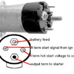
The diagrams for ignition wiring illustrate the wiring used in the power supply of the vehicle. Each component has four distinct colored connections. For accessories, red is the starter solenoid’s color, yellow for battery and blue for accessory. The “IGN terminal” is used to run the wipers, and other operating features. The diagram shows how you can connect the ACC and ST terminals to the rest of the components.
The terminal BAT holds the battery. The electrical system can’t start without the battery. Furthermore the switch won’t come on. If you’re not sure the exact location where the battery in your car is situated, you can examine your wiring diagram to see how to locate it. The ignition switch and battery are connected via accessory terminals. The BAT Terminal is connected to the Battery.
Certain ignition switches have an additional position in which users can modify their outputs as well as control them without the need to use the ignition. Sometimes, customers want to use an auxiliary output independent of the ignition. You can utilize the additional input by connecting the connector to the ACC terminal. This is a useful feature, but there is an important distinction. Most ignition switches are set up to have an ACC status when the vehicle is at the ACC or START positions.
Gallery of 1969 Chevy C10 Ignition Switch Wiring Diagram
Gallery of 1969 Chevy C10 Ignition Switch Wiring Diagram


