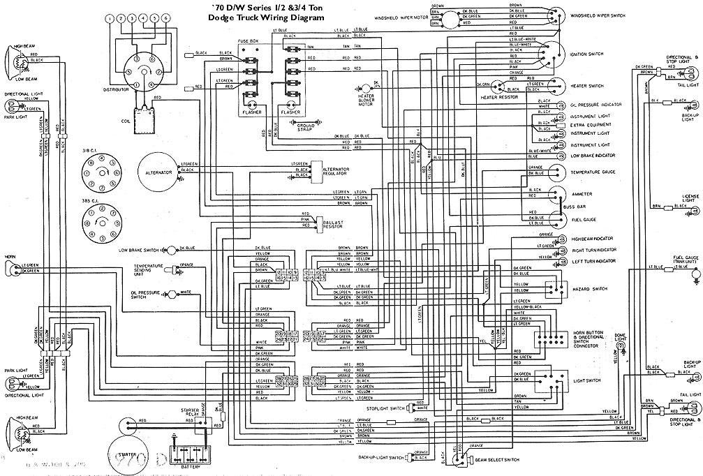
1970 Dodge Dart Ignition Wiring Diagram – Let’s begin by looking at the different types terminals found in an ignition switch. These terminals include the Ignition switch as well as the Coil and the Accessory. Once we’ve established the purpose of these terminals, we will be able to recognize the various parts of the ignition wiring. In addition, we will discuss the functions of the Ignition switch and Coil. Then, we’ll focus on the accessory terminals.
Terminals of ignition switch
An ignition switch has three switches that supply the battery’s current to different destinations. The ON/OFF position of the switch that controls the ignition is managed by the third switch, which provides the choke with power when it’s pushed. Different manufacturers have different color codes for different conductors. This is discussed in another article. OMC uses this method. This connector allows the attachment of a speedometer to the ignition switch.
While most ignition switch terminals aren’t original, the numbers for each one may not be in line with the diagram. Examine the electrical continuity first to ensure that they’re connected correctly to the ignition switch. This can be accomplished using a simple multimeter. After you’re sure that the wires are in good continuity and you are able to connect the new connector. The wiring loom of the ignition switch supplied by the factory will be different from the one that you have in your car.
Before you can connect the ACC outputs to your car’s auxiliary outputs It is essential to know the fundamentals of these connections. The ACC and IGN terminals are the default connection on your ignition switch. the START and IGN terminals are the primary connections for stereo and radio. The ignition switch is the one that controls the engine of your car. Older vehicles are identified with the initials “ACC”, “ST”, (for individual magneto cables) on their ignition switch terminals.
Terminals for coil
The first step to determine the kind of ignition coil is to know the terminology that is used. A simple diagram of the wiring will show a variety of terminals and connections which include two primary terminals and two secondaries. Each coil comes with its own operating voltage. To determine the type of coil you’ve got first, you need to test the voltage at S1, which is the primary terminal. S1 should also be checked for resistance to determine whether it’s an A, Type B or A coil.
The coil’s low-tension side should be connected to the chassis’s less. This is also the ground in the wiring diagram for ignition. The high-tension component supplies the spark plugs with positive. For suppression purposes the body of the coil is required to be connected to the chassis. It is not required to connect electrically. It is also possible to see the connections between the positive and negative coil’s terminals on the ignition wiring diagram. Sometimes, a malfunctioning ignition coil is identified through a scan performed at an auto parts shop.
The black-and-white-striped wire from the harness goes to the negative terminal. The positive terminal is connected to the white wire, which has the trace of black. The contact breaker is attached to the black wire. To confirm the connection, employ a paperclip, or a pencil to lift them out of the plug housing. It’s also essential to make sure that the terminals don’t bend.
Accessory terminals
The ignition wiring diagrams illustrate the various wires utilized to power the vehicle’s various components. There are typically four different colors-coded terminus of each part. The red color is used for accessories, yellow is for the battery, and green is for the solenoid for starters. The “IGN” terminal is used to start the car, turn on the wipers, as well as other features. The diagram shows how you can connect the ACC and ST terminals to the other components.
The terminal BAT holds the battery. The electrical system can’t begin without the battery. A dead battery can make the switch stop turning on. The wiring diagram will show you the location of your car’s battery. The ignition switch is connected to the battery of your car. The BAT connector is connected to the battery.
Some ignition switches feature an “accessory” position that allows users to regulate their outputs without needing to turn on the ignition. In some cases, users may want to use the auxiliary input separately from the ignition. In order for the auxiliary output be used, connect the connector to the same shade as that of the ignition. Then , connect it to the ACC end of the switch. Although this is a great option, there’s a thing you should know. Some ignition switches are configured to be in an ACC position when the vehicle has moved into the ACC position. They’ll also be in the START mode after the vehicle has been entered the IGN position.
Gallery of 1970 Dodge Dart Ignition Wiring Diagram
Gallery of 1970 Dodge Dart Ignition Wiring Diagram


