1971 Plymouth Fury3 Ignition Wiring Diagram – First, we will examine the various types of terminals found in the ignition switch. These are terminals for the Ignition, Coil, or Accessory. Once we’ve determined the function of the terminals it is possible to determine the various components of the ignition wiring. In addition, we will discuss the functions of the Ignition switch and Coil. Then we’ll discuss the Accessory Terminals.
Terminals for ignition switches
There are three different switches in the ignition switch, and they transmit the battery’s current voltage to a variety of destinations. The first switch is the one that supplies power to the choke while the second switch controls the on/off state of the switch. Different manufacturers have different color-coding schemes to identify different conductors. We’ll discuss this in a separate article. OMC uses this method. The adapter is attached to the ignition switch, allowing for the addition of a Tachometer.
Even though most ignition switch terminals don’t carry an original number, they may have a different number. Check the electrical continuity first to ensure that they’re properly connected to the ignition switch. This can be checked using a cheap multimeter. Once you are satisfied that the wires are in good order, you can attach the new connector. If you have an ignition switch that is supplied by the manufacturer the wiring loom may be distinct from the one that is you have in your car.
For connecting the ACC outputs to the auxiliary outputs of your vehicle, you have to understand how these two connections work. The ACC/IGN connections function as the default connections on the ignition switch. The START/IGN terminals connect to the stereo or radio. The ignition switch switches the engine of your car ON and off. In older vehicles the terminals of the ignition switch are identified with the alphabets “ACC” and “ST” (for distinct magnetic wires).
Terminals for coil
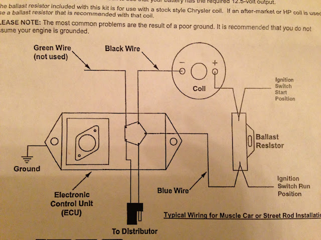
Understanding the terms utilized is the initial step in determining what kind of ignition coil you need. A basic ignition wiring diagram will display a range of terminals and connections which include two primary terminals and two secondaries. You must determine the type of coil that you own by examining the voltage on the primary terminal S1. To determine if the coil is a Type A, C or B coil, it is recommended to also check the resistance of S1.
The coil with low tension must be connected at the chassis’s less. This is the wiring diagram you will see in the wiring diagram. The high-tension side supplies positively directly to the spark plugs. It is essential for the purpose of suppression that the body of the coil’s metal be connected to its chassis however, it is not necessary. The diagram of the ignition wiring will also show you how to connect the positive and negative coil terminals. In certain instances you’ll discover that the ignition coil is damaged and can be diagnosed with scanning at an auto parts store.
The black-and-white-striped wire from the harness goes to the negative terminal. The other white wire has a black trace on it and it connects to the positive terminal. The black wire is connected to the contact breaker. If you’re not certain about the connection between the twowires, use a paper clip to remove them from the housing of the plug. Also, see that the terminals aren’t bent.
Accessory terminals
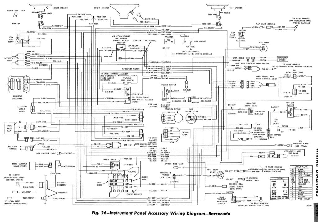
Diagrams of ignition wiring show the wiring used to provide power to various components of the car. There are generally four terminals with color codes that are connected to each component. The accessories are red and the battery yellow, and the starter solenoid green. The “IGN” terminal allows you to start your car, operate the wipers or other functions. The diagram illustrates the connection between the ACCand ST terminals.
The terminal BAT is where the battery is. Without the battery, the electrical system does not start. Also, the switch won’t turn on without the battery. If you’re not sure where your car’s battery is located, you can review your wiring diagram to figure out how to locate it. The accessory terminals on your car connect to the battery and the ignition switch. The BAT terminal is connected with the battery.
Certain ignition switches have an additional position. This allows users to access their outputs from a different place without the ignition. Sometimes, customers would like the output of the auxiliary to be operated independently of the ignition. Make use of the secondary output by connecting it to the ACC terminal on the switch using the same colors. This is a great convenience feature however, there’s one differentiator. Most ignition switches come with the ACC position when the car is in ACC mode and a START position when you are in IGN.
Gallery of 1971 Plymouth Fury3 Ignition Wiring Diagram
Gallery of 1971 Plymouth Fury3 Ignition Wiring Diagram


