1972 Camaro Ignition Switch Wiring Diagram – The first step is to take a look at the different kinds of terminals on the ignition switch. These are the terminals for the Ignition, Coil, or Accessory. After we’ve identified the terminals used and which ones are not, we can recognize the various parts of the 1972 Camaro Ignition Switch Wiring Diagram. We’ll also go over what functions are available for the Ignition switch, as well as the Coil. Following that, we’ll shift our attention to the Accessory terminals.
The ignition switch’s terminals
An ignition switch is comprised of three switches. They transmit the battery’s voltage to different locations. The first switch provides the choke with power when it is pushed. The second is the ignition switch’s ON/OFF position. Different manufacturers use different color-coding methods for different conductors. We’ll discuss this in another article. OMC uses this system. A tachometer adapter is installed on the ignition switch that allows the installation of an Tachometer.
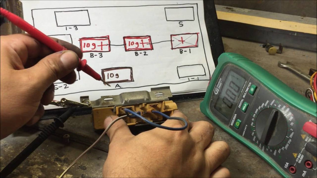
While the majority of the ignition switch terminals may not be original, the numbers for each one may not be in line with the diagram. To ensure that the wires are connected to the switch, it is recommended to check their continuity. A multimeter that is inexpensive can help you do this. Once you’re satisfied with the continuity, you can place the new connector. The wiring loom of a factory-supplied ignition system switch is different.
Understanding how ACC outputs connect to the other outputs inside your vehicle is crucial. The ACC and IGN connectors are the default connections for your ignition switch. The START, IGN, and ACC terminals are the primary connections to the radio or stereo, the START/IGN terminals are the most important ones. The ignition switch is responsible to turn the car’s engines on and off. The terminals on older cars ignition switches are marked with “ACC” as well as ST (for specific magneto wires).
Coil terminals
The first step to determine the kind of ignition coil is to understand the terminology employed. There are a variety of connections and terminals within a basic ignition wiring schematic that include two primary as well as two secondary. The operating voltage of every coil is different. This is why it is essential to first check the voltage at the S1 (primary terminal). S1 should also undergo resistance tests to determine if it are a Type A or B coil.
The chassis’ negative needs to be connected to the low-tension side. This is also the ground in the diagram of ignition wiring. The high-tension part provides positive direct to the sparkplugs. It is required for suppression purposes that the body of the coil’s metal be connected to the chassis, however, it is not necessary. The wiring diagram for the ignition will explain how to connect the terminals of the positive and negative coils. In certain cases, a scan at your local auto parts store will help identify defective ignition coils.
The black-and-white-striped wire from the harness goes to the negative terminal. The white wire also is black with a trace on it and connects to the positive terminal. The contact breaker is linked to the black wire. You can take the black wire from the housing of the plug with a paper clip in case you are uncertain about the connection. It is also important to make sure that the terminals don’t bend.
Accessory Terminals
The ignition wiring diagrams illustrate the different wires that are used to power the car’s various components. Each component is equipped with four distinct color-coded connections. The red color is for accessories, yellow to the battery, and green for the starter solenoid. The “IGN” terminal is used to start the car, controlling the wipers and other functions. The diagram illustrates how you can connect ACC or ST terminals, and other.
The terminal BAT is the connection for the battery. The electrical system can’t be started without the battery. In addition, the switch will not start. To find your car’s battery, check your wiring diagram. The accessory terminals in your car are connected to the battery and the ignition button. The BAT Terminal is connected to the Battery.
Some ignition switches have an “accessory” setting that allows users to control their outputs without needing to utilize the ignition. Some customers prefer to utilize an additional output independent of the ignition. The auxiliary output is connected to connect the connector in the same color as your ignition and connecting it to the ACC terminal of the switch. This feature is convenient, but it has one major difference. The majority of ignition switches are set to be in an ACC position when the car is in the ACC position, while they’re set to the START position when the vehicle is in the IGN position.
Gallery of 1972 Camaro Ignition Switch Wiring Diagram
Gallery of 1972 Camaro Ignition Switch Wiring Diagram


