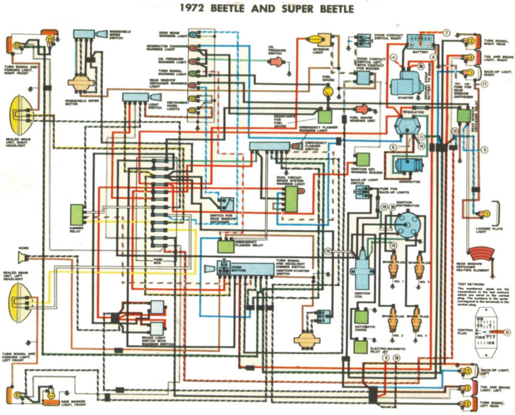
1972 Vw Beetle Ignition Switch Wiring Diagram – The first step is to examine the various terminals that are used in the ignition switch. These include the terminals that are for the Ignition switch, Coil, and Accessory. Once we’ve determined the function of the terminals we can recognize the various parts of the ignition wiring. In addition, we will discuss the functions of both the Ignition Switch and the Coil. After that, we’ll turn our attention to Accessory terminals.
Terminals for ignition switch
There are three switches on an ignition switch, which provide the battery’s voltage to various locations. The first switch is the one that supplies the choke with power, and the third switch toggles the on/off status of the ignition switch. Different manufacturers have their own color-coding system for the various conductors, which is explained in a different article. OMC utilizes the same system. The connector allows for the attachment of a speedometer to the ignition switch.
Although the majority of ignition switch terminals are not authentic, the numbering of each might not be consistent with the diagram. Examine the integrity of the wires first to ensure they’re properly connected to the ignition switch. This can be done using a simple multimeter. When you’re happy with the continuity then you can connect the new connector. If your car has an original ignition switch supplied by the factory (or an electrical loom), the wiring loom might differ from that of the car.
Understanding how the ACC outputs connect to the other outputs of your vehicle is crucial. The ACC terminals as well as the IGN terminals serve as the primary connections to your ignition switch. The START and IGN connections are the main connections for radio and stereo. The ignition switch switches the engine of your car ON and OFF. Older vehicles are identified with the initials “ACC”, “ST”, (for individual magneto cables) on their ignition switch terminals.
Terminals for coil
The first step in determining the type of ignition coil is to understand the terminology used. In a basic ignition wiring diagram there are several different connections and terminals, such as two primary and two secondary. The voltage that operates on every coil is different. Therefore, it is crucial to test the voltage at S1 (primary terminal). S1 must also go through resistance testing to determine whether it is a Type A or B coil.
The chassis’ negative must be connected to the side of low-tension. This is the ground in the wiring diagram for ignition. The high tension side supplies positive power directly to the spark plugs. It is required for suppression purposes that the metallic body of the coil is connected to its chassis, however, it is not necessary. The wiring diagram will depict the connection between positive and negative coil terminals. Sometimes, a malfunctioning ignition coil is identified by a scan done at an auto repair shop.
The black-and-white-striped wire from the harness goes to the negative terminal. The other white wire has a black color and connects to the negative terminal. The black wire is connected to the contactbreaker. You can check the connections with a paperclip to pull the wires out from the housing. Make sure you don’t bend the connectors.
Accessory terminals
The diagrams for ignition wiring depict the wires that are used to power the vehicle’s electrical supply. Each component is equipped with four distinct colored connections. The red symbol represents accessories, yellow for the battery, and green for the starter solenoid. The “IGN” terminal lets you start the car, manage the wipers, or any other features that operate. This diagram demonstrates how to connect ACC and ST terminals to the rest of components.
The terminal BAT is where the battery is. The electrical system is not able to start without the battery. Additionally, the switch won’t begin to turn on. If you’re not sure of the exact location where the battery in your car is situated, look at your wiring diagram to figure out where it is. The accessory terminals in your car are connected with the battery and the ignition button. The BAT Terminal is connected to the battery.
Certain ignition switches provide the option of an “accessory position” which allows users to adjust their outputs independently of the ignition. Sometimes, customers may wish to use the auxiliary output separately from the ignition. To allow the auxiliary output to be used, plug in the connector in the same shade as that of the ignition. Connect it to the ACC end of the switch. This feature is convenient however it does have one major differentiator. Some ignition switches are programmed to have an ACC position when the vehicle has been moved into the ACC position. They will also be in the START position once the vehicle is moved into the IGN position.
Gallery of 1972 Vw Beetle Ignition Switch Wiring Diagram
Gallery of 1972 Vw Beetle Ignition Switch Wiring Diagram


