1974 Camaro Ignition Wiring Diagram – The first step is to examine the various terminals that are used in the ignition switch. These include the terminals that are for the Ignition switch, Coil, and Accessory. Once we’ve established the purpose of the terminals it is possible to recognize the various parts of the ignition wiring. Then, we will discuss the functions and the Coil. We’ll then turn our attention to the accessory terminals.
The ignition switch’s terminals
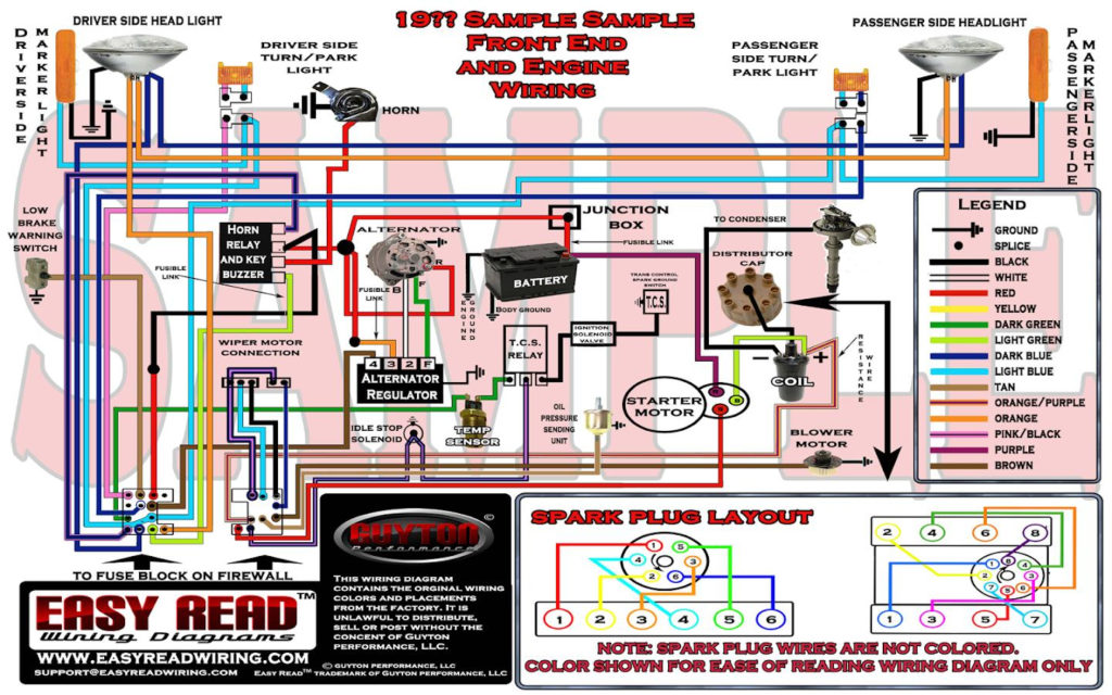
An ignition switch contains three separate switches that feed the battery’s current to different destinations. The first switch supplies power to the choke and the third switch toggles the status of the ignition switch. Different manufacturers have distinct colors-coding systems to match the conductors. OMC uses this method. Connectors can be attached to the ignition switch in order to include an electronic Tachometer.
Although the majority of ignition switch terminals are duplicated, the numbers might not be in line with the diagram. Before plugging into the ignition switch, be sure to test the continuity. This can be checked with a simple multimeter. When you are satisfied with the continuity of the wires it is time to connect the new connector. If your car has an original factory-supplied ignition switch (or an electrical loom) the wiring loom will differ from that of the car.
Before you can connect the ACC outputs to your car’s auxiliary outputs it is crucial to know the fundamentals of these connections. The ACC, IGN and START terminals are the default connections to the ignition switch. They also function as the primary connections to your radio and stereo. The ignition switch turns the car’s engine on and OFF. Older cars are identified with the initials “ACC”, “ST”, (for individual magneto cables) at their ignition switch terminals.
Terminals for coil
Understanding the terminology that is used is the first step towards determining what kind of ignition coil to choose. There are a variety of connections and terminals in a basic ignition wiring schematic that include two primary and two secondary. The operating voltage of every coil is different. This is why it is crucial to test the voltage at S1 (primary terminal). You should also test S1 for resistance to identify if it’s an A, B, or C coil.
The coil’s low-tension side should be connected to the chassis’ minus. This is exactly what you can find in the diagram of wiring. The high-tension component supplies positively directly to the spark plugs. For suppression purposes the coil’s body metal must be connected with the chassis. It’s not necessary for electrical use. The diagram of the ignition wiring will also reveal the connections between the positive and negative coil’s terminals. In some cases it is recommended to conduct a scan at your local auto parts shop will be able to diagnose defective ignition coils.
The black-and-white-striped wire from the harness goes to the negative terminal. The white wire is black-colored and goes to the terminal opposite. The contact breaker is connected to the black wire. It is possible to check the connections with a paperclip to take the wires out from the housing. Make sure you ensure that the terminals have not been bent.
Accessory terminals
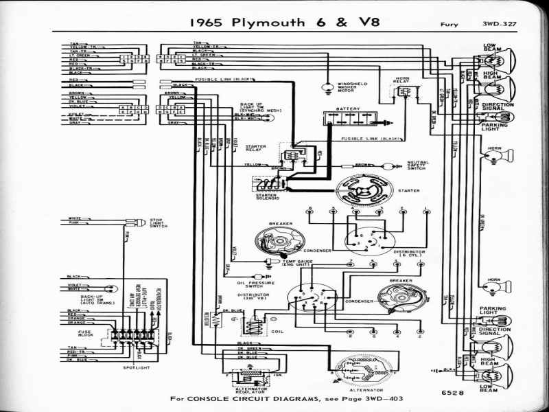
Ignition wiring diagrams show the different wires that are utilized to power the vehicle’s various components. There are typically four colors of terminals connected to each part. Red is used to indicate accessories, yellow the battery, and green the starter solenoid. The “IGN terminal is used to start the car, operating the wipers and other functions. The below diagram shows how to connect both the ACC terminal as well as the ST terminals to other components.
The battery is attached to the terminal called BAT. The electrical system won’t start if the battery isn’t connected. Additionally the switch isn’t turned on. If you’re not sure of where your car’s battery is situated, you can review the wiring diagram of your car to determine where it is. The accessory terminals in your car connect to the ignition switch and the battery. The BAT terminal is connected to the battery.
Some ignition switches offer the option of an “accessory position” that lets users alter their outputs without the ignition. Some customers prefer to make use of an additional output independent of the ignition. To allow the auxiliary output to be used, wire the connector with the same color as the ignition. Then , connect it to the ACC end of the switch. This is a great feature, however there’s an important distinction. Many ignition switches have the ACC position when the car is in the ACC mode, and a START position when the switch is in IGN.
Gallery of 1974 Camaro Ignition Wiring Diagram
Gallery of 1974 Camaro Ignition Wiring Diagram


