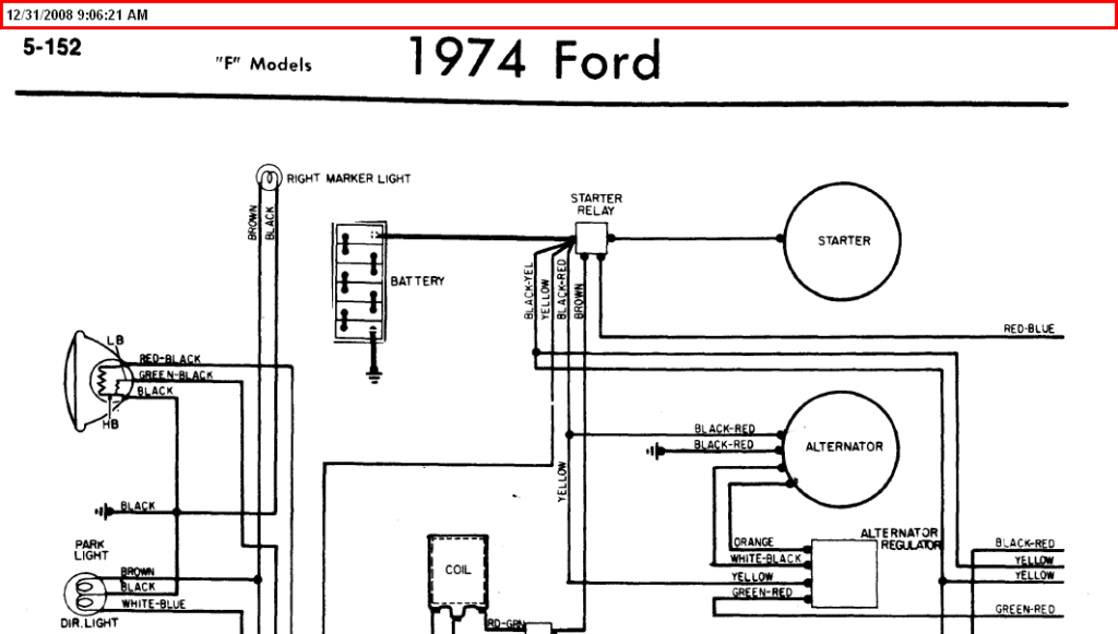
1974 Ford Ignition Switch Wiring Diagram – Let’s start by looking at different kinds of terminals that are found on an ignition switch. These include the terminals that are for the Ignition switch, Coil, and Accessory. Once we know the purpose of these terminals are used for then we can discover the various components of the 1974 Ford Ignition Switch Wiring Diagram. We’ll also go over what functions are available for the Ignition switch and the Coil. Then, we will turn our attention towards the accessories terminals.
The ignition switch’s terminals
Three switches are located on the ignition switch. Each of these three switches feeds the battery’s voltage to a variety of places. The first one is utilized to drive the choke by pushing it, while the second is for the ON/OFF position. Different manufacturers employ various color codes for the different conductors. This is described in a separate article. OMC uses this approach. The connector allows for the attachment of a speedometer the ignition switch.
While most ignition switch terminals aren’t original, the numbers for each might not be consistent with the diagram. The first step is to check the continuity of all wires to ensure they are correctly plugged into the ignition switches. This can be checked with a simple multimeter. When you’re satisfied that the wires are running in good harmony, you can attach the new connector. The wiring loom of the ignition system switch supplied by the manufacturer is distinct.
To connect the ACC outputs to the auxiliary outputs on your vehicle, you have to first understand how these two connections work. The ACC terminals and IGN terminals function as the primary connections to the ignition switch. The START and IGN connections are the main connections for stereo and radio. The ignition switch is responsible for turning the car’s engine to and off. In older vehicles the ignition switch’s terminals are identified with the alphabets “ACC”, and “ST” (for the individual magnet wires).
Terminals for coil
Understanding the terminology that is used is the initial step to finding out the right kind of ignition coil you need. The diagram of the basic ignition wiring depicts various connections and terminals. There are two primary and secondary connections. The operating voltage of each coil is different. Therefore, it is important to first test the voltage at the S1 (primary terminal). You should also examine S1 for resistance to determine whether it is an A, B, or C coil.
The coil’s low-tension side is to be connected to the chassis’ positive. This is also the ground in the ignition wiring diagram. The high-tension end is a positive connection to the sparkplugs. The body of the coil has to be connected to the chassis for suppression purposes, but it is not electrically essential. A wiring diagram can also depict the connection between positive and negative coil terminals. It is possible to find an issue with your ignition coil that can be easily diagnosed by scanning it in the auto parts shop.
The black-and-white-striped wire from the harness goes to the negative terminal. The positive terminal receives the other white wire, which has a trace in black. The black wire connects to the contact breaker. It is possible to check the connections using a paperclip to take the wires out from the housing. Make sure you verify that the connections have not been bent.
Accessory terminals
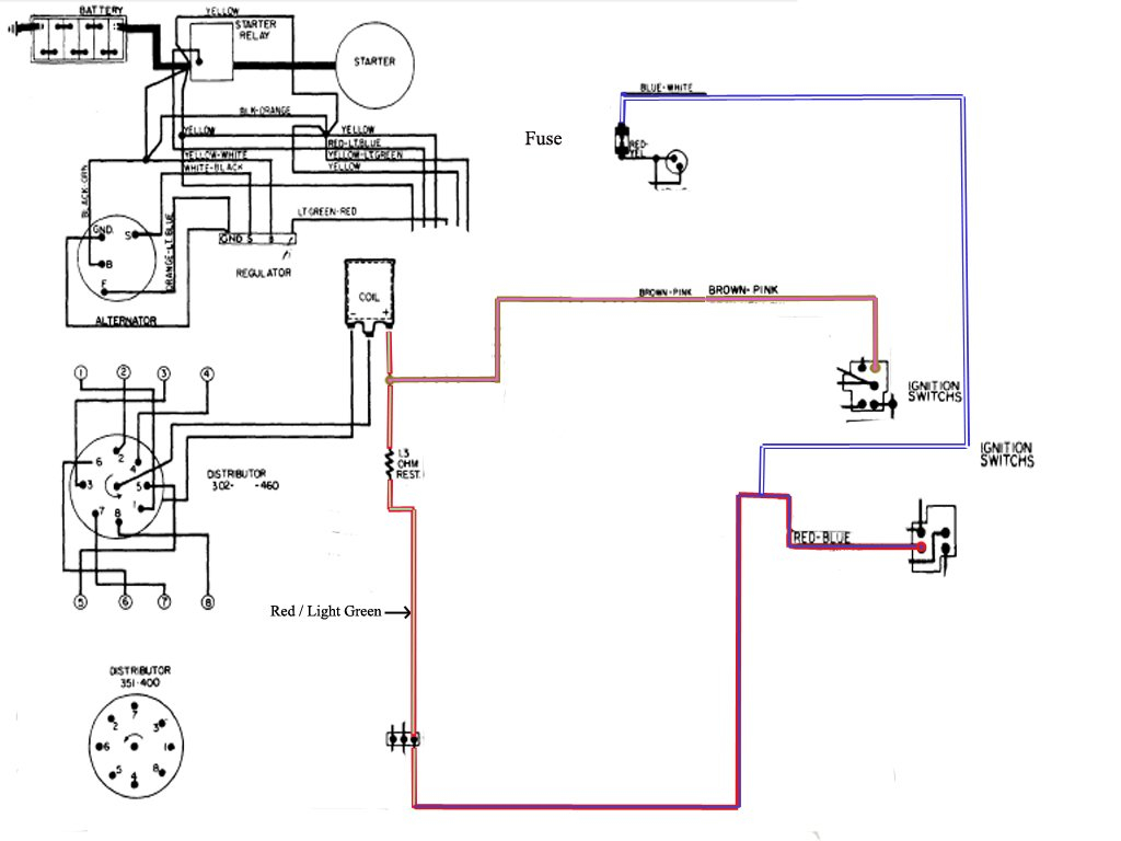
The wiring diagrams for the ignition show the different wires that power the various components of the vehicle. There are generally four colored terminus lines for each component. To identify accessories, red is for starter solenoid, blue for battery, and blue for accessories. The “IGN” terminal can be used to start the car , and also to operate the wipers as well as other operational features. The diagram shows how you can connect the ACC and ST terminals to the other components.
The terminal BAT connects the battery to the charger. The electrical system won’t start in the event that the battery isn’t connected. A dead battery could make the switch not turn on. If you don’t know where your car’s battery is situated, you can examine your wiring diagram to figure out how to locate it. The ignition switch is linked to the car’s battery. The BAT Terminal is connected to the battery.
Certain ignition switches come with the “accessory” setting that permits users to control their outputs without having to use the ignition. Sometimes, users want to use an auxiliary output that is not connected to the ignition. You can use the additional input by connecting it to the ACC terminal. This option is useful, but it has one significant difference. Many ignition switches can be configured to be in an ACC location when the car has moved into the ACC position. They also will be in START mode after the vehicle has been entered the IGN position.
Gallery of 1974 Ford Ignition Switch Wiring Diagram
Gallery of 1974 Ford Ignition Switch Wiring Diagram


