1977 Cj5 Ignition Wiring Diagram – We’ll begin by looking at different types terminals found on an ignition switch. These are terminals for the Ignition, Coil, or Accessory. Once we know what these terminals are then we can determine the various components in the ignition wiring. We will also discuss the roles of the Ignition switch and Coil. After that, we will focus on the accessories terminals.
Ignition switch terminals
The ignition switch consists of three switches. These are the ones that supply the battery’s energy to various locations. The ON/OFF state of the ignition switch is controlled by the first switch, which supplies the choke with power when it’s pushed. Different manufacturers have different color-coding schemes for different conductors. This will be covered in a separate article. OMC follows the same system. A connector can be added to the ignition switch to add an electronic tachometer.
Although some ignition switch terminals could not be original, the numbers of each one might not be in line with the diagram. You should first check the continuity of the wires to see if they are plugged into the correct ignition switch. A multimeter is a good instrument to verify the continuity. After you’re sure that the wires are in good order then you can connect the new connector. The wiring loom used in a factory-supplied ignition system switch differs.
Before connecting the ACC outputs to your car’s auxiliary outputs, it is important to understand the basics of these connections. The ACC and IGN connectors are the default connections for your ignition switch. The START, IGN, and ACC terminals are primary connections to the radio or stereo, the START/IGN connections are the most important ones. The ignition switch is responsible to turn the car’s engines on and off. Older vehicles have ignition switch terminals marked “ACC” or “ST” (for individual magnetowires).
Terminals for coil
The terminology used to determine the kind and model of the ignition coil is the first thing. You will see several connections and terminals in the basic wiring diagram for ignition which includes two primary and two secondary. The coils come with a distinct operating voltage. The initial step to determine which one you have will involve testing the voltage at S1, the main terminal. To determine if the coil is an A, C or B coil, it is recommended to also test S1’s resistance.
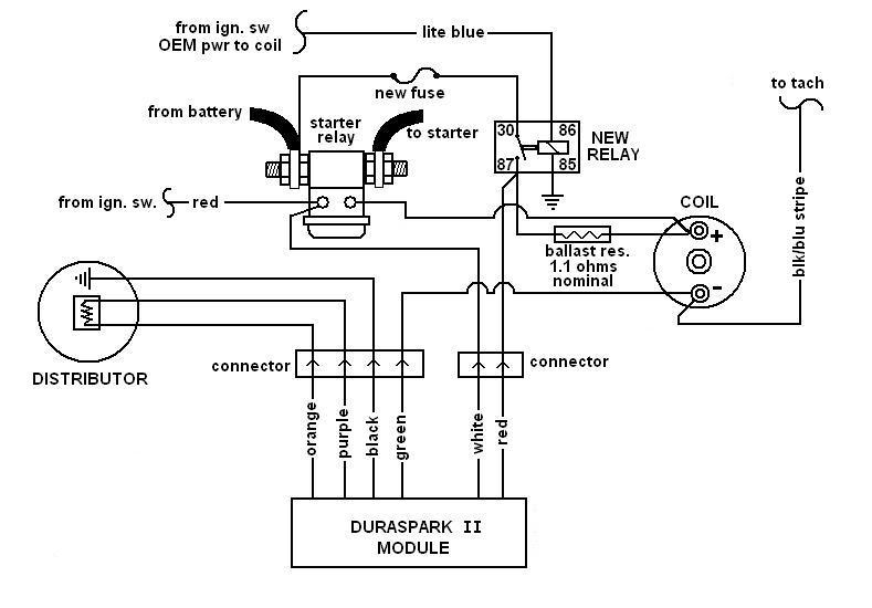
The coil’s low-tension end is to be connected to the chassis positively. This is the ground in the wiring diagram for ignition. The high-tension part is a positive connection to the sparkplugs. To prevent noise, the coil’s body metal must be connected with the chassis. It’s not necessary to use electricity. A wiring diagram can depict the connection between positive and negative coils. You may find an issue with the ignition coil which can be identified by looking it up at an auto parts retailer.
The black-and-white-striped wire from the harness goes to the negative terminal. The positive terminal is connected to the white wire and the black trace. The contact breaker is connected to the black wire. You can remove the black wire from the housing of the plug with a paper clip in case you are uncertain about the connection. It’s also essential to make sure that the terminals do not bend.
Accessory terminals
The ignition wiring diagrams illustrate the different wires used to power the various components of the vehicle. There are typically four color-coded terminals that correspond to each component. The accessories are colored red and the battery yellow and the starter solenoid green. The “IGN” terminal lets you start the car, control the wipers or other functions. The diagram illustrates how you can connect ACC or ST terminals, and other.
The terminal BAT holds the battery. Without the battery the electrical system will not begin. In addition, the switch will not begin to turn on. It is possible to refer to your wiring diagram if you are unsure where your car’s batteries are located. The accessory terminals in your car are connected to the ignition switch, as well as the battery. The BAT connector connects to your battery.
Certain ignition switches come with an accessory setting where users can adjust their outputs as well as control them without having to turn on the ignition. Customers sometimes want the auxiliary output to be used independently from the ignition. To use the additional output, wire the connector using the same colors as ignition and connect it to the ACC terminal on the switch. Although this is a great option, there’s a thing you need to know. A majority of ignition switches feature an ACC position when the car is in the ACC mode, and a START position when it is in IGN.
Gallery of 1977 Cj5 Ignition Wiring Diagram
Gallery of 1977 Cj5 Ignition Wiring Diagram


