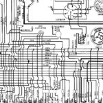
1977 Corvette Ignition Wiring Diagram – First, let’s take a look at the different types of terminals that are used in the ignition switch. The terminals are the Ignition switch and Coil as well as the Accessory. After we’ve identified what these terminals do then we can identify the different parts in the ignition wiring. In addition, we will discuss the function of the Ignition switch, and Coil. After that, we’ll turn our attention to the Accessory terminals.
Terminals of ignition switch
An ignition switch contains three different switches that direct the battery’s current to different destinations. The first is used to turn on the choke by pushing it, and the second is for the ON/OFF setting. Different manufacturers use different colors-coding systems to match the conductors. OMC employs this system. The adapter is attached to the ignition switch to allow for the addition of a Tachometer.
While many ignition switch terminals do not appear in their original configuration, the numbering may not be in line with the diagram. Check the continuity of the wires to ensure that they are plugged into the correct ignition switch. A cheap multimeter can assist you in this. When you’re happy with the continuity, you can place the new connector. The wiring loom for an ignition switch that’s supplied by the factory will be different from the one in your car.
Before connecting the ACC outputs to the auxiliary outputs of your car It is essential to know the fundamentals of these connections. The ACC, IGN and START terminals are the default connection to the ignition switch. They are also the main connections to the radio and stereo. The ignition switch’s function is to turn the engine of your car on and off. Older cars have the ignition switch’s terminals that are labeled “ACC” or “ST” (for individual magnetowires).
Terminals for coil
To identify the kind of ignition coil, the first step is to understand the terms. A basic diagram of the wiring will show you a number of connections and terminals. The coils come with a distinct operating voltage, and the first step in determining which type you’re using is to test the voltage of S1 the primary terminal. S1 should also be tested for resistance in order to identify if it’s a Type B, B or A coil.
The negative of the chassis must be connected to the low-tension side. It is also the ground for the diagram of ignition wiring. The high-tension part supplies the spark plugs with positive. To reduce the noise the body of the coil is required to be connected to the chassis. It is not necessary to electrically connect. The wiring diagram will also illustrate the connection between the positive and negative coil terminals. In some instances, you’ll find that a malfunctioned ignition coil can be diagnosed with scans at an auto parts shop.
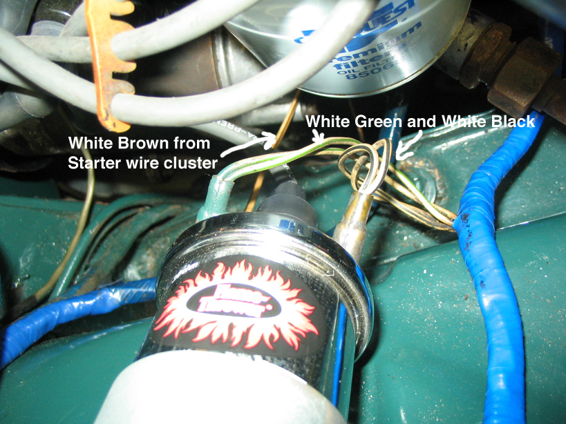
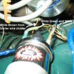
The black-and-white-striped wire from the harness goes to the negative terminal. The other white wire has a black color and connects to the terminal opposite. The black wire connects to the contact breaker. To test the wires’ connections, use a paperclip and lift them off the housing. Also, make sure to ensure that the terminals haven’t been bent.
Accessory terminals
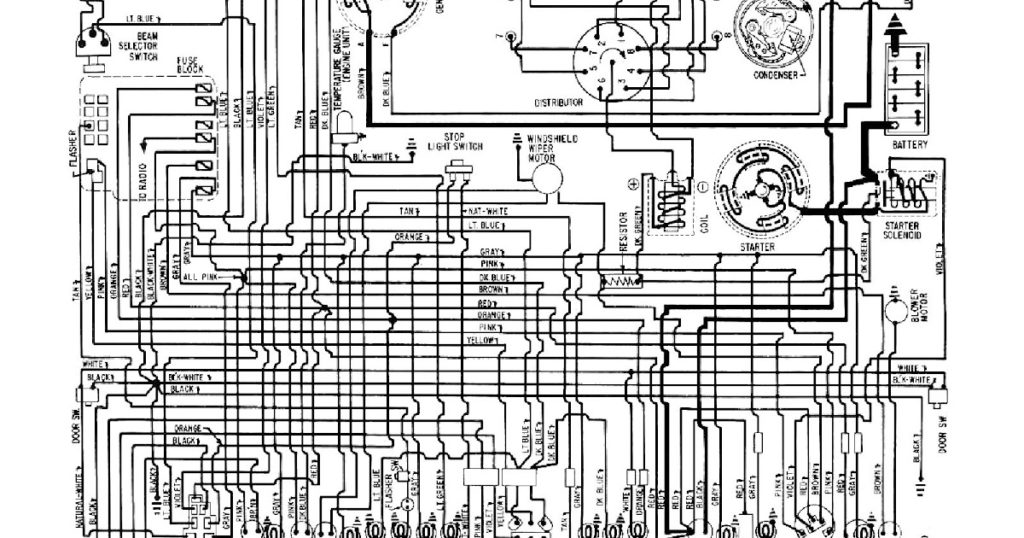
The wiring diagrams of the ignition illustrate the different wires that power the various components of the car. There are typically four different color-coded terminus for each component. Red stands for accessories, yellow is for the battery and green for the starter solenoid. The “IGN terminal” is used to power the wipers along with other operational features. The diagram shows how to connect the ACC and ST terminals to the other components.
The battery is connected to the terminal called BAT. The battery is necessary for the electrical system to start. Additionally, the switch will not start without the battery. If you’re not sure of the location of your car’s battery located, you can examine the wiring diagram of your car to determine how to locate it. Your car’s accessory terminals connect to the ignition switch, as well as the battery. The BAT terminal connects to the battery.
Some ignition switches have an “accessory” position that permits users to control their outputs , without needing to utilize the ignition. Users may wish to use the auxiliary output in addition to the ignition. You can use the secondary input by connecting the connector to the ACC terminal. This is a useful option, but there’s one important distinction. The majority of ignition switches are set up to show an ACC status when the car’s in either the ACC or START positions.
Gallery of 1977 Corvette Ignition Wiring Diagram
Gallery of 1977 Corvette Ignition Wiring Diagram


