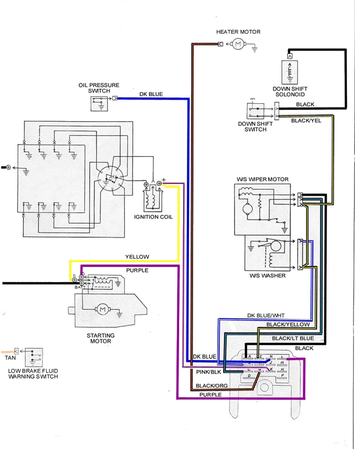
1978 Camaro Ignition Switch Wiring Diagram – Let’s begin by examining the different types and purposes of the terminals on the ignition switches. These are the terminals for the Ignition, Coil, or Accessory. After we’ve identified the purpose of the terminals we will be able to determine the various components of the ignition wiring. We’ll also discuss the functions and the Coil. Then, we’ll talk about the functions of the ignition switch and Coil.
Terminals for ignition switches
An ignition switch is comprised of three switches. They transmit the voltage of the battery to many different places. The first is utilized to turn on the choke through pushing it, and another switch controls the ON/OFF position. Different manufacturers employ various color codes for the different conductors. This is discussed in a separate article. OMC follows this scheme. The ignition switch also includes a connector for adding an Tachometer.
While most ignition switch terminals are duplicated, the number may not be in line with the diagram. To ensure that your wires are plugged in to the ignition switch, you must verify their continuity. This can be accomplished using a simple multimeter. After you’re happy with the continuity of the wires install the new connector. If your vehicle is equipped with an ignition switch installed the wiring diagram may differ.
Understanding how ACC outputs connect to the other outputs inside your car is vital. The ACC terminals as well as the IGN terminals function as the standard connections for your ignition switch. The START and IGN connections are the most important connections for radio and stereo. The ignition switch is the engine’s off/on button. Older cars are equipped with ignition switch terminals labeled “ACC” or “ST” (for individual magnetowires).
Terminals for coil
The first step to determine the type of ignition coil is to understand the terms employed. There are a variety of connections and terminals within a basic ignition wiring schematic, including two primary, as well as two secondary. The coils come with a distinct operating voltage, and the first step in determining which type you’re using is to test the voltage of S1 the primary terminal. S1 must also go through resistance tests to determine if it’s a Type A or B coil.
The chassis’ negative should be connected to the coil’s low-tension end. This is the wiring diagram you will see in the wiring diagram. The high-tension supply supplies the spark plugs with positive electricity directly. It is essential to suppress the coil’s metallic body be connected to its chassis but not essential. A wiring diagram can also illustrate the connection between the positive and negative coils. In certain instances, you’ll find that the ignition coil is damaged and is identified by scanning at an auto parts shop.
The black-and-white-striped wire from the harness goes to the negative terminal. The white wire is the other one. It is black with a trace on it, and connects to the positive terminal. The black wire is connected to the contact breaker. To verify the connections, employ a paperclip, or a pencil to remove them of the plug housing. It’s also essential to make sure the terminals aren’t bent.
Accessory terminals
Ignition wiring diagrams depict the various wires that are used to power the various components. There are generally four color-coded terminals to each component. The red color is used for accessories, yellow is for the battery, while green is the solenoid for starters. The “IGN terminal lets you start your car, operate the wipers, and any other functions. The diagram illustrates the connection of the ACCas well as ST terminals.
The terminal BAT holds the battery. The electrical system can’t begin without the battery. Furthermore, the switch won’t begin to turn on. To locate your car’s battery look over your wiring diagram. The accessory terminals in your car are connected with the battery and ignition button. The BAT terminal is connected to the battery.
Certain ignition switches provide an additional “accessory position” that allows users to modify their outputs independent of the ignition. Some customers may prefer to use the auxiliary output independently of the ignition. You can use the additional output by connecting it to an ACC terminal on your switch that has the same color. This is a useful feature, but there is an important distinction. The majority of ignition switches are designed to have an ACC status when the vehicle is at either the ACC or START position.
Gallery of 1978 Camaro Ignition Switch Wiring Diagram
Gallery of 1978 Camaro Ignition Switch Wiring Diagram


