1979 Ford F250 Ignition Wiring Diagram – First, we will take a look at the various kinds of terminals that are found on the ignition switch. They are terminals for Coil, Ignition Switch, and Accessory. Once we know the terminals that are utilized, we can begin to identify the different components of the 1979 Ford F250 Ignition Wiring Diagram. We’ll also be discussing the functions of the Ignition switch, and Coil. We will then concentrate on the accessories terminals.
Terminals for the ignition switch
There are three switches in an ignition switch, which feed the battery’s voltage to several different destinations. The first switch is the one that supplies the choke with power, and the third switch toggles the on/off state of the switch. Different manufacturers use their own color-coding systems for the various conductors, which is explained in a different article. OMC utilizes this procedure. A connector is also included in the ignition switch to allow attaching a Tachometer.
Even though most ignition switch terminals don’t carry an original number, they may have a different number. To make sure that your wires are plugged in to the switch, you should check their continuity. A multimeter is a good tool to test the continuity. After you have verified that the wires are in good condition, you are able to install the connector. If your vehicle has an original ignition switch supplied by the factory (or wiring loom) The wiring loom might differ from that in your vehicle.
For connecting the ACC outputs to the auxiliary outputs of your car, you’ll need to understand the way these two connections function. The ACC and IGN terminals are the default connections on your ignition switch. the START and IGN terminals are the main connections for the radio and stereo. The ignition switch is the one that turns the engine of your car on and off. Older cars are equipped with ignition switch’s terminals that are labeled “ACC” or “ST” (for individual magnetowires).
Terminals for Coil
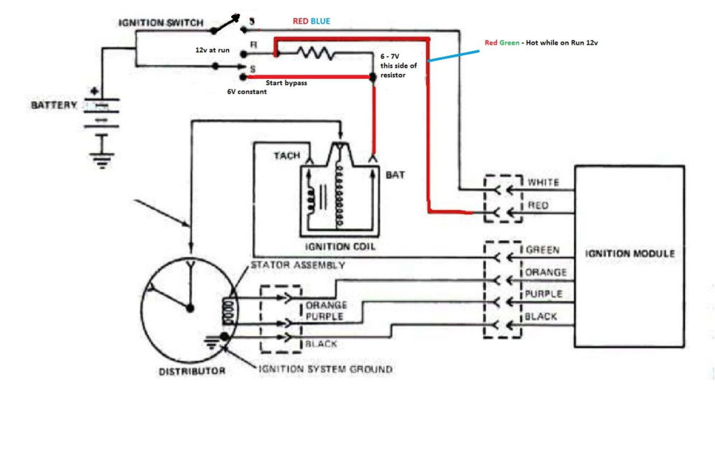
Understanding the terms utilized is the initial step to finding out the right kind of ignition coil you need. You’ll see a number of connections and terminals on an ignition wiring schematic which includes two primary and two secondary. The voltage that operates on each coil is different. Therefore, it is important to first test the voltage at S1 (primary terminal). You should also examine S1 for resistance in order to identify if it’s an A or B coil.
The coil’s low-tension side is to be connected to the chassis’ positive. This is what’s called the ground on the diagram of ignition wiring. The high-tension side supplies the positive power direct to the spark plugs. It is essential for suppression purposes that the metallic body of the coil is connected to its chassis but not essential. The diagram of the ignition wiring will also demonstrate the connection of the positive and negative coil’s terminals. In some instances you’ll discover that the ignition coil is damaged and can be diagnosed with a scan at an auto parts store.
The black-and-white-striped wire from the harness goes to the negative terminal. The positive terminal receives the white wire and a trace of black. The black wire connects to the contact breaker. If you’re not certain about the connections of both, you can use the clip of a paperclip to remove them from the plug housing. It’s also essential to make sure that the terminals do not bend.
Accessory terminals
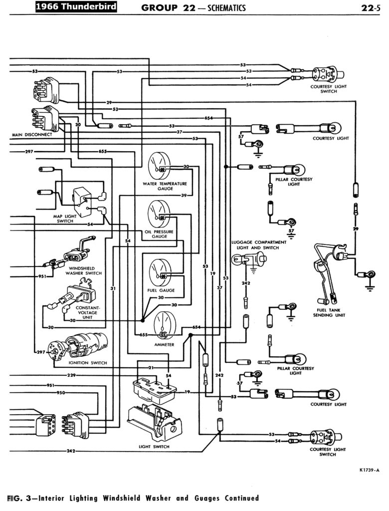
The ignition wiring diagrams illustrate the different wires used to are used to power various components of the car. Each component has four distinct connections that are color coded. Red is used to indicate accessories, yellow the battery, and green the starter solenoid. The “IGN terminal” is used to power the wipers as well as other operating features. This diagram shows how you can connect ACC and ST terminals with the other components.
The terminal BAT holds the battery. The electrical system is not able to begin without the battery. The switch won’t be able to turn on if there is no battery present. You can refer to your wiring diagram if uncertain about where the car’s batteries are. The ignition switch is connected to the battery of your car. The BAT terminal is connected to the battery.
Some ignition switches feature an independent “accessory” position, in which users can control their outputs without the ignition. Sometimes, customers want to use an auxiliary output that is not connected to the ignition. To make use of the auxiliary output, wire the connector with the same colors as the ignition, and connect it to the ACC terminal on the switch. This feature is convenient, but it has one major differentiator. The majority of ignition switches are configured to show an ACC status when the car is in the ACC or START positions.
Gallery of 1979 Ford F250 Ignition Wiring Diagram
Gallery of 1979 Ford F250 Ignition Wiring Diagram


