1979 Ford Ignition Module Wiring Diagram – We’ll begin by looking at the different types terminals found on an ignition switch. These terminals are used for the Ignition button, Coil and Accessory. Once we know the purpose of these terminals, we will be able to identify the various parts of the ignition wiring. We will also talk about the functions and the Coil. Then, we’ll focus on the accessory terminals.
The terminals of the ignition switch
The ignition switch has three switches. They feed the voltage of the battery to different locations. The first one is utilized to power the choke through pushing it, while the second is for the ON/OFF position. Different manufacturers have distinct colors-coding systems to match the conductors. OMC follows this scheme. The connector permits the attachment of a speedometer the ignition switch.
Although the majority of ignition switch terminals do not have an original number, they might have a different one. Verify the integrity of the wires first to ensure they’re connected correctly to the ignition switch. You can do this with an inexpensive multimeter. After you’re satisfied with the connection it’s time to connect the new connector. The wiring loom for an ignition switch that’s factory-supplied will be different than the one that you have in your vehicle.
It is important to understand the ways in which the ACC outputs and the auxiliary outputs function to connect them. The ACC/IGN terminals function as the default connections on the ignition switch. The START/IGN connections connect to the radio or stereo. The ignition switch turns the engine of your car ON and OFF. Older vehicles are identified with the letters “ACC”, “ST”, (for individual magneto cables) at the ignition switch’s terminals.
Terminals for coil
Understanding the terminology is the initial step to finding out what kind of ignition coil you have. An understanding of the basic wiring diagram for ignition will show you a number of connections and terminals. The voltage that operates on each coil is different. This is why it is essential to first check the voltage at S1 (primary terminal). S1 should also undergo resistance testing to determine whether it is an A or B coil.
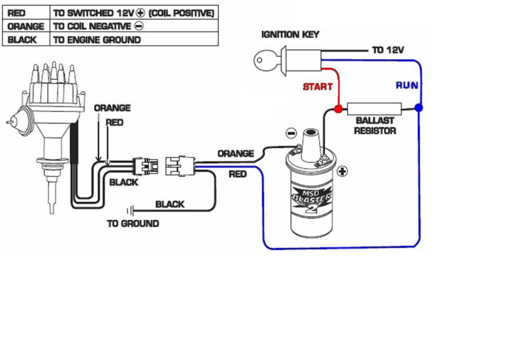
The coil’s low-tension component must be connected with the chassis positive. This is the wiring diagram you will find in the wiring diagram. The high tension side supplies positively directly to the spark plugs. The aluminum body of the coil needs to be connected to the chassis to prevent it from being smothered however it’s not electrically required. It is also possible to see the connections of the positive and negative coil terminals on the ignition wiring diagram. You may find an issue with the ignition coil which can be identified by looking it up at the auto parts shop.
The black-and-white-striped wire from the harness goes to the negative terminal. The other white wire has a black trace, and connects to the positive terminal. The black wire connects to the contact breaker. If you’re not sure about the connection between the two, try using the clip of a paperclip to remove them from the plug housing. Be sure that you don’t bend the connectors.
Accessory terminals
Diagrams of ignition wiring depict the wiring used to power various parts of the car. There are usually four colored terminus lines for each component. To identify accessories, red stands the starter solenoid’s color, yellow for battery, and blue for accessories. The “IGN terminal allows you to start the car, manage the wipers, or any other operation features. The diagram shows how to connect ACC or ST terminals, and other.
The terminal known as BAT is the place where the battery is. The electrical system cannot begin without the battery. Also, the switch won’t turn on without the battery. A wiring diagram can tell you the location of the battery of your car. The ignition switch as well as the battery are connected by the accessory terminals. The BAT terminal is connected to the battery.
Some ignition switches feature an “accessory” position that permits users to control their outputs , without having to use the ignition. Sometimes, customers may wish to utilize the auxiliary output separately from the ignition. It is possible to use the secondary input by connecting the connector to the ACC terminal. Although this is a great feature, there’s something you need to know. The majority of ignition switches are set to have an ACC position when the vehicle is in the ACC position, but they’re set to the START position when the vehicle is in the IGN position.
Gallery of 1979 Ford Ignition Module Wiring Diagram
Gallery of 1979 Ford Ignition Module Wiring Diagram


