1980 Camaro Ignition Wiring Diagram – We will first look at the various types and purposes of the terminals in the ignition switches. These include the terminals for the Ignition switch, Coil, and Accessory. Once we’ve determined the function of these terminals, we can recognize the various parts of the ignition wiring. We will also discuss the roles of the Ignition switch and Coil. The next step is to focus to the accessory terminals.
Terminals for the ignition switch
The ignition switch consists of three different switches. These are the ones that supply the battery’s power to several destinations. The first one supplies the choke with power when pushed, and the second is the position of the ignition switch’s ON/OFF. Each manufacturer has its own color-coding system, which we’ll discuss in a subsequent article. OMC uses the same method. The adapter is attached to the ignition switch to allow for the addition of the tonometer.
Even though most ignition switch terminals don’t carry an original number, they might have a different one. Before you plug in the ignition switch, ensure that you check the continuity. This can be checked using a cheap multimeter. After you’re sure that the wires are in good order then you can connect the new connector. The wiring loom for an ignition switch that’s supplied by the manufacturer will differ from the one you have in your car.
Before you can connect the ACC outputs to your car’s auxiliary outputs it is crucial to know the fundamentals of these connections. The ACC and IGN terminals are the default connections for your ignition switch, and the START and IGN terminals are the main connections to the radio and stereo. The ignition switch controls the car’s engine. On older vehicles, the ignition switch terminals are marked with the alphabets “ACC”, and “ST” (for distinct magnet wires).
Terminals for coil
The first step to determine the type of ignition coil is to comprehend the terms employed. An ignition wiring diagram will reveal a variety of connections and terminals, including two primary and two secondaries. Each coil has a specific operating voltage. To determine the type of coil you own, the first step is to test the voltage at S1, which is the primary terminal. To determine if it is an A, C, or B coil, you must also test S1’s resistance.
The chassis’ negative must be connected to the side of low-tension. This is the base of the ignition wiring. The high-tension supply delivers positive directly to spark plugs. The aluminum body of the coil has to be linked to the chassis to prevent it from being smothered but isn’t required. A wiring diagram can depict the connection between positive and negative coil terminals. In some cases it is recommended to conduct a scan at your local auto parts store will be able to diagnose defective ignition coils.
The black-and-white-striped wire from the harness goes to the negative terminal. The positive terminal receives the white wire, which has an black trace. The black wire connects to the contactbreaker. You can take the black wire from the plug housing with a paper clip if you are unsure about the connections. Be sure that the terminals aren’t bent.
Accessory terminals
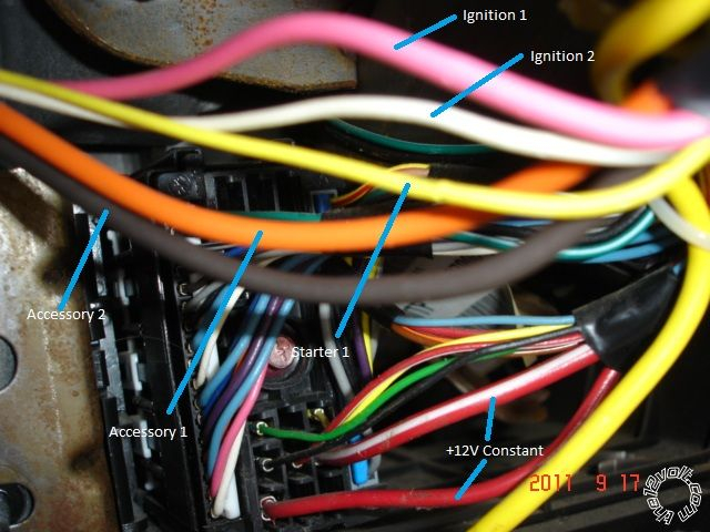
Diagrams of the ignition wiring illustrate the wires used to provide power to various components of the car. There are usually four different color-coded terminals to each component. Accessories are red while the battery is yellow, the starter solenoid green. The “IGN terminal” is used to power the wipers as well as other operating features. The below diagram shows how to connect the ACC terminal as well as the ST terminals to the other components.
The terminal BAT holds the battery. The electrical system is not able to begin without the battery. Furthermore, the switch doesn’t turn on. You can refer to your wiring diagram if not sure where the batteries of your car are. The ignition switch is connected to the battery of your car. The BAT terminal is connected to the battery.
Some ignition switches feature a separate “accessory” position, where users can control their outputs without using the ignition. Sometimes, users want to utilize an additional output independent of the ignition. In order to use the auxiliary output, connect the connector in the same colors as ignition connecting it to the ACC terminal on the switch. This option is useful however, it does have one significant differentiator. Some ignition switches are programmed to have an ACC position once the car is in the ACC position. They’ll also be in the START position once the vehicle is entered the IGN position.
Gallery of 1980 Camaro Ignition Wiring Diagram


Gallery of 1980 Camaro Ignition Wiring Diagram


