1980 Kawasaki Kz 440 Igniter Wiring Diagram – First, we will take a look at the various kinds of terminals that are found on the ignition switch. These are terminals for the Ignition, Coil, or Accessory. Once we have identified what these terminals do and what they do, we can then be able to identify the various parts of the ignition wiring. In addition, we will discuss the function of the Ignition switch and Coil. After that, we will concentrate on the accessories terminals.
Terminals of ignition switch
There are three separate switches in an ignition switch, which provide the battery’s voltage to a variety of destinations. The choke is powered by the first switch. The second switch is responsible for the ON/OFF switch of the ignition switch. Every manufacturer has its unique color-coding system, which we’ll go over in a separate article. OMC follows this scheme. The ignition switch comes with an option to connect the timer.
While most ignition switch terminals are not authentic, the numbering of each might not be consistent with the diagram. To ensure that your wires are properly plugged in to the switch, you must verify their continuity. This can be checked using a simple multimeter. When you’re satisfied with the continuity of your wires, you will be able to connect the new connector. If your vehicle has an original factory-supplied ignition switch (or a wiring loom) the wiring loom may differ from that in your car.
In order to connect the ACC outputs to the auxiliary outputs of your vehicle, you have to understand the way these two connections function. The ACC, IGN and START terminals are the default connection to the ignition switch. They are also the primary connections to your radio and stereo. The ignition switch is the one that turns the car’s engine on and off. Older vehicles have ignition switch’s terminals that are labeled “ACC” or “ST” (for individual magnetowires).
Terminals for coil
The first step to determine the type of ignition coil is to know the terms that is used. In a simple ignition wiring diagram there are a number of different connections and terminals, which include two primary and two secondary. It is essential to identify the type of coil that you are using by testing the voltage on the primary terminal, called S1. Also, you should examine S1 for resistance to identify if it’s an A, B, or C coil.
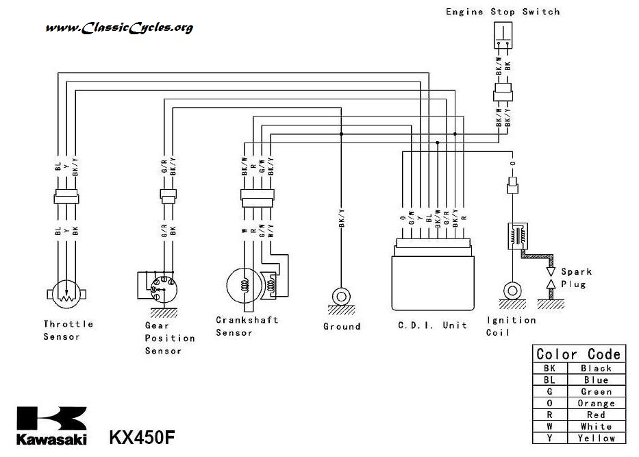
The low-tension coil side must be connected at the chassis’ less. This is also the ground in the diagram of ignition wiring. The high-tension side supplies the spark plugs with positive. To prevent noise the coil’s metal body must be connected with the chassis. This is not necessary for electrical use. A wiring diagram can illustrate the connection between the positive and negative coils. Sometimes, a visit to an auto parts store could diagnose a malfunctioning ignition wire.
The black-and-white-striped wire from the harness goes to the negative terminal. The white wire is black-colored and goes to the negative terminal. The black wire connects to the contactbreaker. It is possible to check the connections with a pencil to take the wires out of the housing. It is also important to make sure the terminals aren’t bent.
Accessory terminals
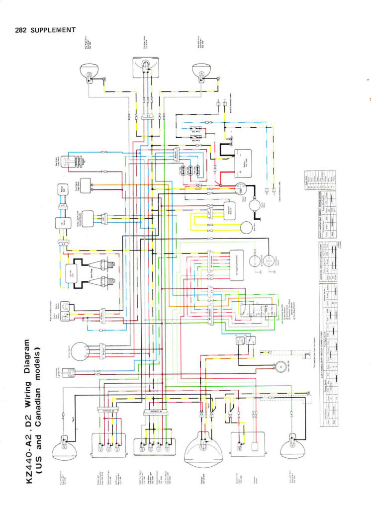
Diagrams of the ignition wiring show the wiring used to provide power to various components of the vehicle. Each component has four distinct colored connections. The red symbol represents accessories, yellow for the battery and green is for the starter solenoid. The “IGN” terminal is used to turn on the car , and also to operate the wipers as well as other operational features. This diagram demonstrates how to connect ACC and ST terminals to the rest of the components.
The terminal BAT is where the battery is. The electrical system cannot begin without the battery. A dead battery could cause the switch to not come on. The wiring diagram will tell you where to find your car’s battery. The accessory terminals on your vehicle connect to the battery and the ignition switch. The BAT Terminal is connected to the Battery.
Certain ignition switches have an additional position. This lets users access their outputs from a different location without having to turn on the ignition. In some cases, users may want to use the auxiliary input independently of the ignition. To use the additional output, wire the connector in identical colors to the ignition, connecting it to the ACC terminal on the switch. This is a useful option, but there’s one important distinction. Many ignition switches can be set to have an ACC position once the car is in the ACC position. They’ll also be in START mode when the vehicle has entered the IGN position.
Gallery of 1980 Kawasaki Kz 440 Igniter Wiring Diagram
Gallery of 1980 Kawasaki Kz 440 Igniter Wiring Diagram


