1982 Jeep Cj5 Ignition Wiring Diagram – We will first look at the various types and functions of the terminals that are found on the ignition switches. They include terminals for the Ignition switch, Coil, and Accessory. After we’ve identified what these terminals are, we will identify the different parts in the ignition wiring. We’ll also discuss the different functions of the Ignition Switch and the Coil. We’ll then turn our attention on the accessory terminals.
Terminals for the ignition switch
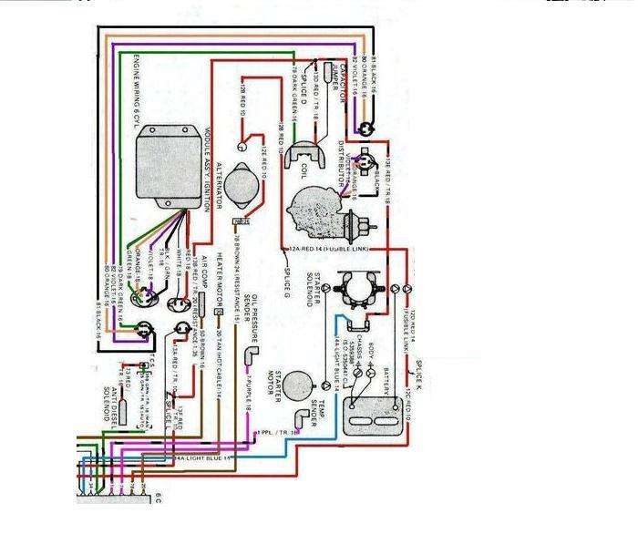
The ignition switch consists of three switches. They are responsible for supplying the battery’s power to several destinations. The first switch provides power to the choke and the third switch toggles the status of the ignition switch. Different manufacturers have different color-coding schemes for different conductors. We’ll discuss this in another article. OMC follows this system. An additional connector is included inside the ignition switch to allow attaching the to a tachometer.
Although the majority of ignition switch terminals do not come in original form The numbering might not match that of the diagram. Verify the electrical continuity first to make sure they’re connected correctly to the ignition switch. This can be checked using a cheap multimeter. Once you are happy with the continuity of the wires, you can install the new connector. If your vehicle has an original factory-supplied ignition switch (or wiring loom), the wiring loom will differ from that of the car.
For connecting the ACC outputs to the auxiliary outputs on your car, you need first know how these two connections work. The ACC and IGN connectors are the default connections of your ignition switch. The START, IGN, and ACC terminals are primary connections for radios or stereo, the START/IGN connections are the primary ones. The ignition switch switches the engine of your car ON and off. The terminals on older cars ignition switches are identified by “ACC” as well as ST (for the individual magneto wires).
Terminals for Coil
Understanding the terminology is the initial step towards determining which type of ignition coil you own. A basic ignition wiring layout will reveal a variety of terminals and connections. The coils come with a distinct operating voltage, and the first method of determining what type you have will involve testing the voltage on S1, the main terminal. To determine whether it’s a Type A, C or B coil you must also test the resistance on S1’s.
The negative of the chassis must be connected to the side of low-tension. It is also the ground in the diagram of ignition wiring. The high-tension part provides the spark plugs with positive. To reduce the noise, the coil’s body metal is required to be connected to the chassis. It’s not necessary to use electricity. There are also connections between the positive and negative coil’s terminals on the ignition wiring diagram. In certain cases, a scan at the local auto parts store will help identify defective ignition coils.
The black-and-white-striped wire from the harness goes to the negative terminal. The terminal that is negative is served by the trace in black that’s connected to the white wire. The black wire connects to the contact breaker. It is possible to remove the black wire from the housing of the plug with a paper clip in case you are uncertain about the connection. Make sure that the terminals do not bend.
Accessory terminals
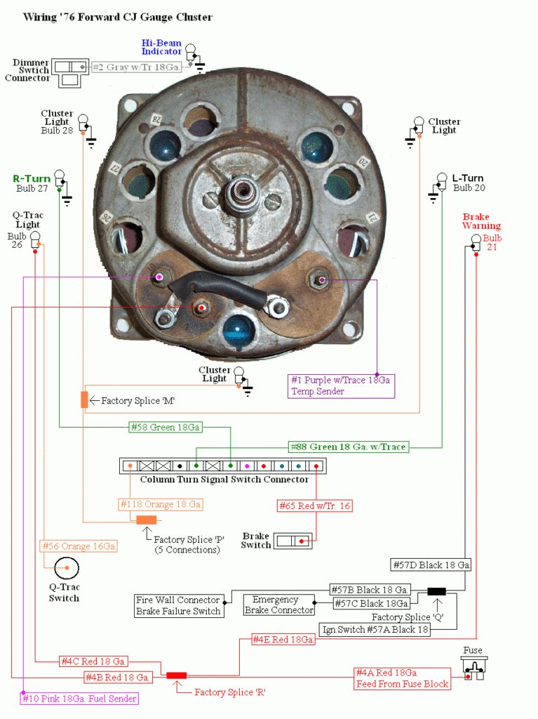
The diagrams for ignition wiring depict the wires that are used to power the vehicle’s electrical supply. Typically there are four color-coded terminals for each component. For accessories, red stands for starter solenoid, yellow for battery and blue for accessory. The “IGN terminal” is used to power the wipers as well as other operating functions. The diagram illustrates how you can connect ACC or ST terminals as well as the rest.
The battery is attached to the terminal whose name is BAT. The battery is vital for the electrical system to get started. A dead battery could make the switch not turn on. A wiring diagram can inform the location of the battery of your car. The accessory terminals of your vehicle are connected to the battery and the ignition switch. The BAT connector is connected to the battery.
Some ignition switches are equipped with an additional position. This allows users to access their outputs from a different place without having to turn on the ignition. Some customers may prefer to use the auxiliary output separately from the ignition. Make use of the auxiliary output by connecting it to the ACC terminal on the switch with the same colors. This is a great convenience feature however there’s a distinction. Most ignition switches are set to operate in the ACC position when the car is in the ACC position, but they’re in the START position when the car is in the IGN position.
Gallery of 1982 Jeep Cj5 Ignition Wiring Diagram
Gallery of 1982 Jeep Cj5 Ignition Wiring Diagram


