1984 Toyota Pickup Ignition Wiring Diagram – The first step is to take a look at the different kinds of terminals for the ignition switch. These terminals are used for the Ignition button, Coil and Accessory. After we’ve identified the purpose of the terminals we can determine the various components of the ignition wiring. In addition, we will discuss the function of the Ignition switch and Coil. After that we will move on to the Accessory Terminals.
Ignition switch terminals
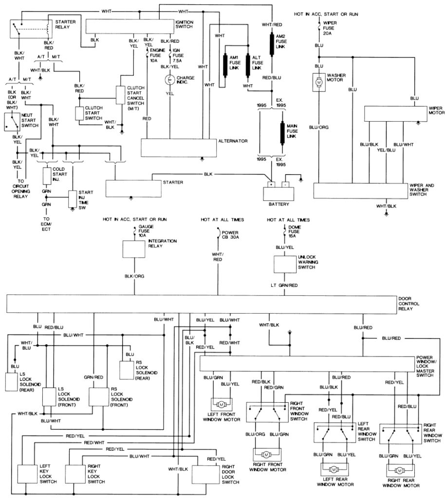
The ignition switch consists of three switches. These are the ones that supply the battery’s energy to various locations. The first one is used to turn on the choke by pushing it, while the third switch is used to control the ON/OFF position. Different manufacturers use different color-coding systems that correspond to the conductors. OMC employs this system. There is a connector in the ignition switch to allow attaching the tachometer.
Although most ignition switch terminals can be duplicated, the numbers might not match the diagram. To make sure that your wires are properly connected to the switch, you must verify their continuity. This can be done with a cheap multimeter. When you are happy with the continuity of the wires, connect the new connector. The wiring loom used for the ignition switch factory-supplied will be different than the one you have in your car.
The first step is to understand the distinctions between ACC and auxiliary outputs. The ACC and IGN terminals are the default connections for your ignition switch. the START and IGN terminals are the primary connections for the radio and stereo. The ignition switch is the one that controls the engine of your car. The terminals for the ignition switch on older vehicles are marked with the initials “ACC” as well as “ST” (for the individual magneto wires).
Terminals for coil
Understanding the terms that is used is the first step in finding out the right type of ignition coil. There are a variety of connections and terminals within a basic ignition wiring schematic that include two primary as well as two secondary. The coils come with a distinct operating voltage, and the first step in determining which type you’re using is to test the voltage on S1, the primary terminal. It is also recommended to examine S1 for resistance in order to determine whether it is an A B, C, or coil.
The low-tension end of the coil needs to be connected to the chassis’ negative. It is also the ground for an ignition wiring diagram. The high tension side supplies positively directly to the spark plugs. The aluminum body of the coil has to be linked to the chassis for suppression, but it isn’t electrically required. It is also possible to see the connections of the positive and negative coil’s terminals on the ignition wiring diagram. Sometimes, a defective ignition coil can be detected with a scan at an auto parts shop.
The black-and-white-striped wire from the harness goes to the negative terminal. The white wire also has a black trace on it and it goes to the positive terminal. The black wire connects to the contactbreaker. You can examine the connections with a pencil to take the wires out from the housing. Be sure to verify that the connections haven’t been bent.
Accessory terminals
Diagrams of the ignition wiring illustrate the wires used to provide power to various components of the vehicle. There are generally four terminals with color codes that are connected to the component. Red is used to indicate accessories, yellow the battery, and green the starter solenoid. The “IGN terminal” is used to power the wipers along with other operational functions. The diagram illustrates how you can connect ACC or ST terminals and the rest.
The terminal BAT is the connector for the battery. The electrical system can’t be started without the battery. Also, the switch won’t start without the battery. A wiring diagram can inform you where to find the battery of your car. The accessory terminals in your car connect to the ignition switch and the battery. The BAT connector connects to your battery.
Some ignition switches come with a separate “accessory” position, in which users can manage their outputs without the ignition. Sometimes, customers want to make use of the auxiliary output separate from the ignition. For the auxiliary output to be used, wire the connector in the same color as that of the ignition. Then connect it with the ACC end of the switch. While this is an excellent option, there’s a thing to be aware of. Most ignition switches are configured to be in an ACC position when the car is in the ACC position, but they’re in the START position when the vehicle is in the IGN position.
Gallery of 1984 Toyota Pickup Ignition Wiring Diagram
Gallery of 1984 Toyota Pickup Ignition Wiring Diagram


