1985 Agway Lawn Mower Ignition Switch Wiring Diagram – Let’s start by looking at the different kinds of terminals that are found on an ignition switch. They are terminals that are used for Coil, Ignition Switch, and Accessory. Once we know the purpose of these terminals are used for, we will proceed to discover the various components of the 1985 Agway Lawn Mower Ignition Switch Wiring Diagram. In addition, we will discuss the roles of the Ignition switch, as well as the Coil. Next, we’ll discuss the function of the Ignition switch as well as Coil.
Terminals for ignition switch
An ignition switch contains three separate switches that feed the battery’s current to various destinations. The choke is powered by the first switch. The third switch regulates the ON/OFF of the ignition switch. Each manufacturer has their own color-coding system, which we will discuss in another article. OMC uses this approach. This connector allows the attachment of a speedometer to the ignition switch.
Even though some of the ignition switch terminals may not be original, the numbering of each may not be in line with the diagram. Before plugging in the ignition switch, be sure to test the continuity. This can be checked using a cheap multimeter. After you’re happy with the integrity of your wires, you will be able to install the new connector. If you have a factory-supplied ignition switch the wiring loom may be different from the one in your car.
Before connecting the ACC outputs to your car’s auxiliary outputs it is crucial to understand the basics of these connections. The ACC/IGN terminals act as the default connections on the ignition switch. The START/IGN terminals are connected to the stereo or radio. The ignition switch is responsible for turning the car’s engine to and off. Older cars have the ignition switch terminals labeled “ACC” or “ST” (for individual magnetowires).
Terminals for coil
Understanding the terms used is the initial step to finding out the right kind of ignition coil to choose. In a basic ignition wiring diagram you’ll see several different connections and terminals, which include two primary and two secondary. Each coil has an operating voltage. The first step to determine which kind of coil you have is to check the voltage on S1, or the primary terminal. To determine whether it’s an A, C or B coil, you should also test the resistance on S1’s.
The coil’s low-tension end is to be connected to the chassis positively. This is what’s called the ground on the wiring diagram for ignition. The high-tension part is a positive connection to the sparkplugs. For suppression purposes the coil’s metal body is required to be connected to the chassis. It’s not necessary to use electricity. The diagram of the ignition wiring will also reveal the connection of the positive and negative coil terminals. You may find an issue with the ignition coil which can be identified by scanning it at the auto parts shop.
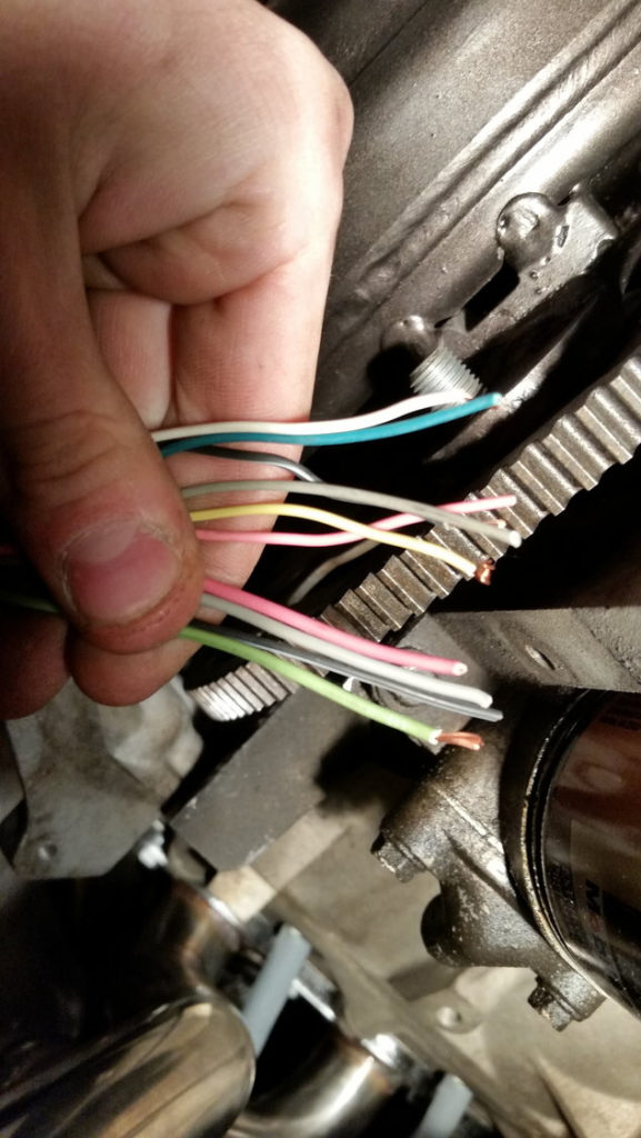
The black-and-white-striped wire from the harness goes to the negative terminal. The other white wire is black-colored and goes to the terminal opposite. The black wire connects with the contact breaker. You can check the connections with a pencil to remove the wires from the housing. It is also important to make sure that the connections aren’t bent.
Accessory terminals
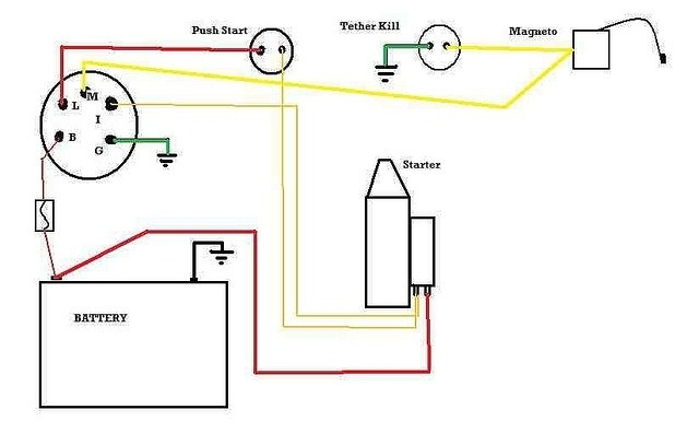
The diagrams for ignition wiring illustrate the wires used to power the vehicle’s electrical supply. Each component is equipped with four distinct connections that are color coded. To identify accessories, red is the starter solenoid’s color, blue for battery, and blue for accessory. The “IGN” terminal can be used to turn on the car, operate the wipers and other functions. The diagram illustrates the connection between the ACCas well as ST terminals.
The terminal called BAT is where the battery is connected. The electrical system will not start in the event that the battery isn’t connected. The switch will not turn on if there is no battery present. A wiring diagram can show you the location of the battery in your car. The ignition switch is connected to the battery of your car. The BAT terminal is connected to the battery.
Certain ignition switches have an additional position. It allows users to connect their outputs to a different place without having to turn on the ignition. Some customers might want to use the auxiliary input independently of the ignition. To make use of the additional output, wire the connector with the same colors as ignition, connecting it to the ACC terminal on the switch. This feature is convenient, but it has one significant differentiator. Many ignition switches have an ACC position when the car is in ACC mode, and a START position when you are in IGN.
Gallery of 1985 Agway Lawn Mower Ignition Switch Wiring Diagram
Gallery of 1985 Agway Lawn Mower Ignition Switch Wiring Diagram


