1985 Dodge Ignition Wiring Diagram – We’ll begin by looking at different types of terminals on an ignition switch. These terminals comprise the Ignition switch and Coil along with the Accessory. After we’ve identified what these terminals do, we will be able to identify the various parts of the ignition wiring. We will also talk about the functions as well as the Coil. We will then discuss the roles of the Ignition switch and Coil.
Terminals for ignition switch
An ignition switch is comprised of three switches. They feed the battery’s voltage to many different locations. The first switch powers the choke. The second switch is responsible for the ON/OFF function of the ignition switch. Different manufacturers have different colour-coding systems that correspond to the conductors. OMC employs this system. The connector allows for the attachment of a speedometer to the ignition switch.
While many ignition switch terminals may not be original, the numbers of each one might not be in line with the diagram. To ensure that your wires are properly plugged in to the ignition switch you should check their continuity. A simple multimeter will aid in this. Once you’re satisfied with the continuity it’s time to connect the new connector. If your vehicle is equipped with an installed ignition switch the wiring diagram will differ.
It is important to know the differences between the ACC and the auxiliary outputs. The ACC/IGN connections function as the default connections for the ignition switch. The START/IGN terminals connect to the radio or stereo. The ignition switch is the one that controls the engine of your car. Older cars have the ignition switch’s terminals that are labeled “ACC” or “ST” (for individual magnetowires).
Terminals for coil
The first step to determine the type of ignition coil is to understand the terminology that is used. In a simple diagram of the wiring for ignition there are several different terminals and connections, including two primary and two secondary. It is essential to identify the type of coil that you are using by testing the voltage at the primary terminal S1. S1 should also be checked for resistance in order to identify if it’s an A, Type B or an A coil.
The chassis’ negative end should be connected to connect the coil’s low-tension side. It is also the ground for an ignition wiring diagram. The high-tension side supplies the positive power directly to the spark plugs. To prevent noise the coil’s metal body is required to be connected to the chassis. This is not necessary for electrical use. The diagram of the ignition wiring will also indicate the connections of the positive coil’s terminals. Sometimes, a visit to an auto parts store could diagnose a malfunctioning ignition wire.
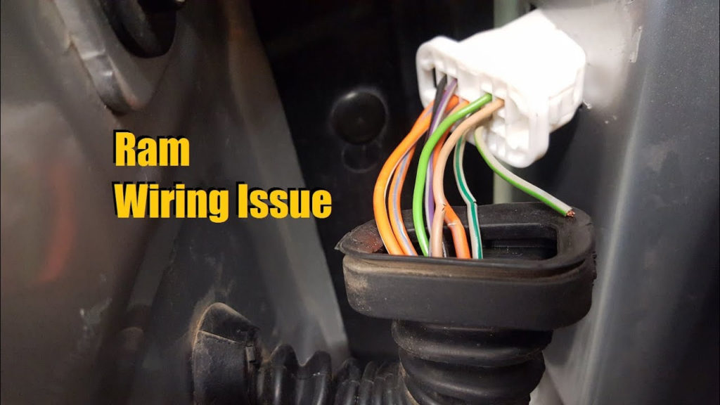
The black-and-white-striped wire from the harness goes to the negative terminal. The other white wire is black with a trace on it and connects to the positive terminal. The black wire connects to the contact breaker. If you’re not sure about the connection between the twowires, use an old paper clip to take them from the plug housing. Also, make sure to check that the terminals aren’t bent.
Accessory terminals
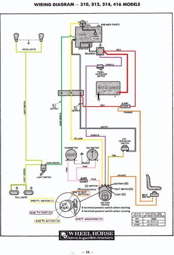
Diagrams of ignition wiring show the different wires used to power various components. There are generally four color-coded terminals that correspond to the component. Red is used to indicate accessories, yellow is the battery, and green for the starter solenoid. The “IGN” terminal is used to start the vehicle and control the wipers as well as other operational features. This diagram demonstrates how to connect ACC and ST terminals with the rest of components.
The terminal known as BAT is the place where the battery is. The electrical system is not able to begin without the battery. The switch will not turn on if there is no battery there. If you don’t know the location of your car’s battery situated, look at the wiring diagram of your car to determine where it is. The accessory terminals of your car are connected to the ignition switch and the battery. The BAT terminal connects to the battery.
Some ignition switches feature the “accessory” setting that allows users to control their outputs without needing to turn on the ignition. Some customers want the output of the auxiliary to be operated independently of the ignition. In order for the auxiliary output be used, wire the connector in the same shade as that of the ignition. Then connect it with the ACC end of the switch. This is a great convenience feature however, there’s one difference. A majority of ignition switches feature the ACC position when the car is in ACC mode, and a START position when you are in IGN.
Gallery of 1985 Dodge Ignition Wiring Diagram
Gallery of 1985 Dodge Ignition Wiring Diagram


