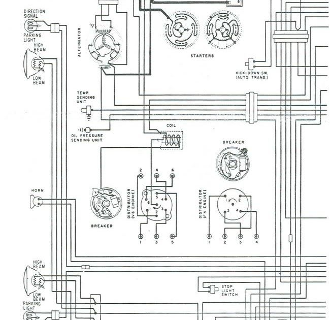
1985 El Camino Ignition Wiring Diagram – First, we will look at the various types of terminals for the ignition switch. These are the terminals for the Ignition, Coil, or Accessory. Once we know what these terminals do, we will determine the various components in the ignition wiring. We will also discuss the functions for the Ignition switch, as well as the Coil. We will then turn our attention towards the accessories terminals.
Terminals for the ignition switch
The ignition switch is comprised of three switches that supply the battery’s power to various locations. The first switch provides the choke with power, while the second toggles the status of the ignition switch. Different manufacturers have different colour-coding systems that correspond to the conductors. OMC follows this scheme. A connector can be added to the ignition switch to include an electronic tachometer.
While many ignition switch terminals may not be original, the numbering of each one might not be in line with the diagram. It is important to first verify the continuity of the wires to ensure that they are connected to the ignition switch correctly. A cheap multimeter can assist you in this. When you’re satisfied with the continuity of the wires, then you’ll be able to install the new connector. If your car has an ignition switch installed the wiring diagram may differ.
In order to connect the ACC outputs to the auxiliary outputs of your vehicle, you have to understand how these two connections work. The ACC and IGN terminals are the default connections for the ignition switch. the START and IGN terminals are the primary connections for stereo and radio. The ignition switch turns the car’s engine on and off. The terminals of older cars ignition switches are identified with “ACC” and ST (for specific magneto wires).
Terminals for coil
Understanding the terminology that is used is the first step towards determining what kind of ignition coil you need. An ignition wiring diagram will reveal a variety of terminals and connections, which include two primary terminals and two secondary. The voltage that operates on every coil is different. This is why it is important to first test the voltage at S1 (primary terminal). To determine if the coil is a Type A, C or B coil, it is recommended to also check the resistance of S1.
The coil with low tension must be connected at the chassis’ minus. This is the wiring diagram you will find in the wiring diagram. The high-tension end is a positive connection to the sparkplugs. It is necessary for the purpose of suppression that the coil’s metallic body be connected to its chassis but not essential. The wiring diagram of the ignition will explain how to connect the terminals of either the positive and negative coils. You may find an issue with the ignition coil that can be easily diagnosed by scanning it at an auto parts store.
The black-and-white-striped wire from the harness goes to the negative terminal. The white wire also has a black trace on it, and connects to the positive terminal. The black wire goes to the contact breaker. You can examine the connections with a paperclip to take the wires out from the housing. Make sure that the connectors do not bend.
Accessory terminals
Diagrams of ignition wiring show the different wires that are utilized to power the vehicle’s various parts. There are usually four colored terminals that correspond to the respective component. To identify accessories, red stands for starter solenoid, blue for battery, and blue for accessory. The “IGN terminal is used to start the car, controlling the wipers, and for other functions. The diagram shows the connection between the ACC- and ST terminals.
The terminal BAT is where the battery is. Without the battery, the electrical system does not start. The switch also won’t turn on without the battery. It is possible to view your wiring diagram to figure out where the batteries of your car are situated. The ignition switch is connected to the battery of your car. The BAT terminal is connected to the battery.
Some ignition switches come with an accessory position. This lets users access their outputs from a different place without the ignition. Sometimes, customers want to utilize an auxiliary output that is separate from the ignition. Make use of the auxiliary output by connecting it to the ACC terminal on the switch using the same colors. Although this is a great option, there’s a thing you need to know. Many ignition switches have an ACC position when the car is in the ACC mode and a START mode when the switch is in IGN.
Gallery of 1985 El Camino Ignition Wiring Diagram
Gallery of 1985 El Camino Ignition Wiring Diagram


