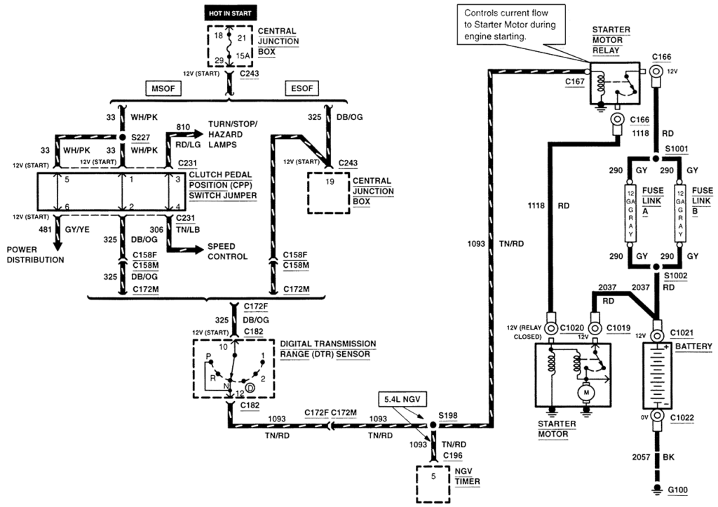
1985 Ford F150 Ignition Switch Wiring Diagram – We’ll begin by looking at different types of terminals on the ignition switch. These are terminals for the Ignition, Coil, or Accessory. Once we have identified the terminals that are utilized then we can recognize the various parts of the 1985 Ford F150 Ignition Switch Wiring Diagram. In addition, we will discuss the function of the Ignition switch and Coil. Then, we will turn our attention towards the accessory terminals.
The terminals are for ignition switches.
Three switches are located in an ignition switch. Each of the three switches feeds the battery’s voltage to various locations. The ON/OFF state of the ignition switch is controlled by the third switch, which supplies the choke with power when it’s pulled. Different manufacturers have different color codes for different conductors. This is discussed in a separate article. OMC utilizes this method. The ignition switch also includes a connector for adding an timer.
While many ignition switch terminals could not be authentic, the numbering of each may not be in line with the diagram. It is important to first verify the electrical continuity to see if they are connected to the correct ignition switch. A multimeter is a great tool to check the continuity. When you’re happy with the quality of the connection it’s time to connect the new connector. If your car is equipped with an original ignition switch supplied by the factory (or an electrical loom) The wiring loom will differ from that in your car.
It is important to understand the ways in which the ACC outputs and auxiliary outputs function to connect them. The ACC terminals as well as the IGN terminals are the default connections to the ignition switch. The START and IGN connections are the primary connections for radio and stereo. The ignition switch is responsible for turning the car’s engine on and off. Older cars have the ignition switch terminals labeled “ACC” or “ST” (for individual magnetowires).
Terminals for coil
Understanding the terminology used is the first step to finding out the right kind of ignition coil to choose. In a simple ignition wiring diagram, you will see various connections and terminals, which include two primary and two secondary. The coils are equipped with a particular operating voltage, and the first step to determine which one you’re using is to test the voltage on S1, the main terminal. S1 must also be inspected for resistance in order to identify whether it’s an A, Type B, or A coil.
The lower-tension side of the coil needs to be connected to the chassis”negative. This is also the ground for the diagram of ignition wiring. The high-tension component supplies positive direct to the spark plugs. For suppression purposes, the coil’s body metal must be connected with the chassis. This is not necessary for electrical use. A wiring diagram can depict the connection between positive and negative coil terminals. In certain instances it is possible to find a malfunctioned ignition coil is identified by scans at an auto parts shop.
The black-and-white-striped wire from the harness goes to the negative terminal. The negative terminal is served by the black trace connected to the white wire. The black wire is connected to the contactbreaker. To verify the connections between the two wires, employ a paperclip to lift them from the housing. You should also check to make sure that the connections are not bent.
Accessory terminals
Diagrams of ignition wiring show the wires that are used in the vehicle’s power supply. Typically there are four distinct colored terminals for each part. Red is used for accessories, yellow is for the battery, and green is the solenoid for starters. The “IGN terminal” is used to provide power to the wipers and other operating functions. This diagram shows how to connect ACC and ST terminals with the rest of the components.
The battery is connected to the terminal named BAT. Without the battery the electrical system can not start. The switch won’t be able to turn on if the battery isn’t present. A wiring diagram can tell the location of your car’s battery. The accessory terminals of your car connect to the ignition switch, as well as the battery. The BAT terminal is connected to the battery.
Certain ignition switches provide the option of an “accessory position” that allows users to adjust their outputs independently of the ignition. Sometimes, customers wish to utilize an auxiliary output that is separate from the ignition. You can use the secondary input by connecting it to the ACC terminal. Although this is a fantastic feature, there’s one thing you need to know. Some ignition switches are configured to be in an ACC position when the vehicle is in the ACC position. They’ll also be in the START mode once the vehicle is entered the IGN position.
Gallery of 1985 Ford F150 Ignition Switch Wiring Diagram
Gallery of 1985 Ford F150 Ignition Switch Wiring Diagram


