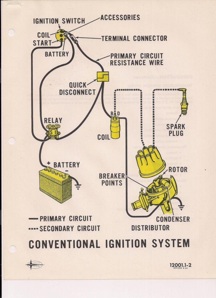
1985 Mustang Ignition Wiring Diagram – Let’s begin by examining the different types and purposes of the terminals on the ignition switches. These terminals comprise the Ignition switch, the Coil along with the Accessory. Once we’ve determined the function of these terminals, we will be able to determine the various components of the ignition wiring. We’ll also discuss the roles of both the Ignition Switch and the Coil. Following that, we’ll shift our attention to the Accessory terminals.
The ignition switch’s terminals
Three switches are located in an ignition switch. Each of these three switches is able to feed the battery’s voltage to a variety of locations. The first switch powers the choke. The second switch controls the ON/OFF function of the ignition switch. Different manufacturers use different color-coding methods for different conductors. We will cover this in another article. OMC uses this system. There is a connector inside the ignition switch for connecting an to a tachometer.
Although some ignition switch terminals could not be authentic, the numbering of each may not be in line with the diagram. Before plugging into the ignition switch, ensure that you check the continuity. A cheap multimeter can help you do this. Once you’re satisfied with the continuity, you can place the new connector. The wiring loom of the ignition switch factory-supplied will be different than the one you have in your car.
Understanding how ACC outputs connect to the other outputs of your car is vital. The ACC and IGN connectors are the standard connections of your ignition switch. The START, IGN, and ACC terminals are the primary connections for radios or stereo, the START/IGN connections are the primary ones. The ignition switch is responsible for turning the engine of your car to and off. Older cars are equipped with ignition switch terminals marked “ACC” or “ST” (for individual magnetowires).
Terminals for coil
To identify the kind of ignition coil you need to know the step is to understand the terminology. The basic ignition wiring diagram shows a number different connections and terminals. There are two primary and one secondary. Each coil has an operating voltage. The first step to determine the kind you’re using is to examine the voltage on S1, or the primary terminal. S1 should also be tested for resistance in order to identify whether it’s an A, Type B, or A coil.
The chassis’ negative end should be connected to the coil’s low-tension side. This is also the ground on an ignition wiring diagram. The high tension side supplies positively directly to the spark plugs. To reduce the noise, the coil’s metal body must be connected to chassis. However, it is not necessary to connect the coil electrically. The diagram of the ignition wiring will also show you the connection of the negative and positive coil terminals. Sometimes, a check at an auto parts shop can diagnose a malfunctioning ignition wire.
The black-and-white-striped wire from the harness goes to the negative terminal. The positive terminal also gets the white wire that includes a black trace. The black wire connects to the contact breaker. To confirm the connection, use a paperclip or a pencil to pull them out of the housing for the plug. Be sure to verify that the connections have not been bent.
Accessory terminals
The wiring diagrams of the ignition illustrate the different wires used to are used to power various components of the car. There are generally four colors of terminals connected to each part. Red refers to accessories, yellow to the battery, and green the starter solenoid. The “IGN” terminal is used to start the car and operate the wipers, as well as other operating features. This diagram shows how to connect ACC and ST terminals to the other components.
The battery is connected to the terminal whose name is BAT. The electrical system won’t start without the battery. The switch will not turn off if the battery isn’t there. To locate your car’s battery examine the wiring diagram. The accessory terminals in your car are connected to the battery and ignition button. The BAT Terminal is connected to the Battery.
Certain ignition switches provide the option of an “accessory position” that allows users to alter their outputs without the ignition. Customers sometimes want the auxiliary output to be used separately from the ignition. You can use the additional input by connecting it to the ACC terminal. Although this is a fantastic option, there’s a thing to be aware of. Some ignition switches are configured to be in an ACC position when the vehicle has moved into the ACC position. They will also be in START mode when the vehicle has moved into the IGN position.
Gallery of 1985 Mustang Ignition Wiring Diagram

Gallery of 1985 Mustang Ignition Wiring Diagram


