1986 Camaro Ignition Wiring Diagram – We will first examine the different types of terminals for the ignition switch. They are terminals that are used for Coil, Ignition Switch, and Accessory. After we’ve identified the terminals used, we can begin to recognize the various parts of the 1986 Camaro Ignition Wiring Diagram. We will also discuss the functions of the Ignition switch and Coil. Then we’ll move on to the Accessory Terminals.
Terminals for the ignition switch
An ignition switch has three switches. They transmit the voltage of the battery to many different places. The first switch powers the choke. The third switch regulates the ON/OFF switch of the ignition switch. Different manufacturers have different color-coding schemes for different conductors. We’ll discuss this in a separate article. OMC uses this method. There is a connector inside the ignition switch to allow attaching a tachometer.
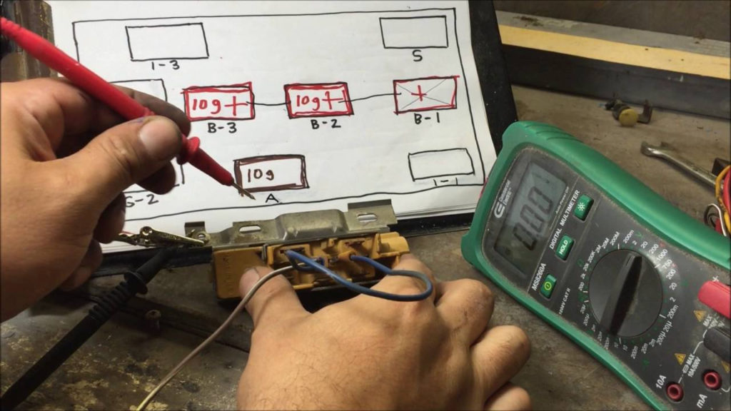
Even though most ignition switch terminals do not have an original number, they may be equipped with a different number. Before plugging in the ignition switch, make sure to check the continuity. A cheap multimeter can help you do this. After you’re satisfied with the integrity of the wires install the new connector. The wiring loom used for the ignition switch supplied by the factory will be different from the one that you have in your car.
It is important to know the differences between the ACC and secondary outputs. The ACC/IGN terminals function as the default connection on the ignition switch. The START/IGN terminals connect to the stereo or radio. The ignition switch is accountable to turn the engine of your car on and off. The terminals of the ignition switch on older cars are identified with the letters “ACC” and “ST” (for each magneto wires).
Terminals for coil
Understanding the terms is the first step to knowing what type of ignition coil you own. A basic ignition wiring layout will show you a number of terminals and connections. Each coil is equipped with a distinct operating voltage. To determine which type of coil you have, the first step is to determine the voltage at the S1 primary terminal. S1 should also be checked for resistance to determine if it’s an A, Type B or A coil.
The chassis’ negative end should be connected to the coil’s low-tension side. This is what is known as the ground for the ignition wiring. The high-tension component supplies the spark plugs with positive. The metal body of the coil needs to be connected to the chassis for suppression purposes however it isn’t electrically required. It is also possible to see the connections of the positive and the negative coil terminals on the diagram of the ignition wiring. You may find an ignition coil problem which can be identified by looking it up at an auto parts retailer.
The black-and-white-striped wire from the harness goes to the negative terminal. The terminal for the negative is served by the trace in black that’s joined to the white wire. The black wire is connected to the contact breaker. It is possible to check the connections with a pencil to pull the wires out of the housing. Also, make sure to check that the terminals haven’t been bent.
Accessory terminals
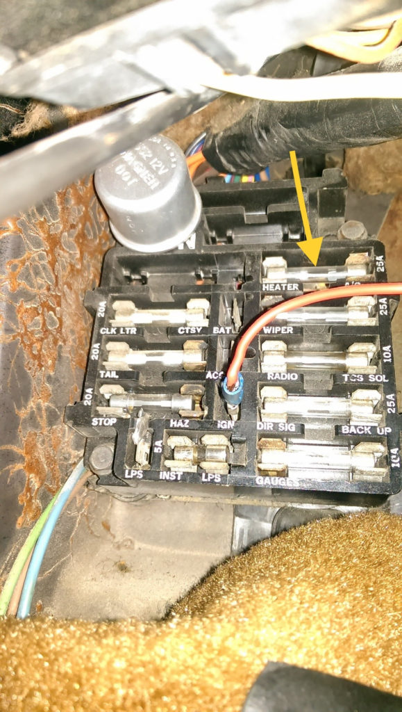
Diagrams of ignition wiring illustrate the wires used to supply power to different parts of the vehicle. There are usually four color-coded terminus for each component. The red symbol represents accessories, yellow for the battery and green for the starter solenoid. The “IGN” terminal can be utilized to turn on the car, turn on the wipers, and other functions. The diagram shows the connection between the ACCas well as ST terminals.
The battery is connected to the terminal named BAT. The electrical system won’t start without the battery. In addition, the switch will not begin to turn on. A wiring diagram can inform you where to find the battery in your car. The accessory terminals in your vehicle connect to the battery as well as the ignition switch. The BAT connector is connected to your battery.
Some ignition switches feature the “accessory” position that allows users to control their outputs without having to use the ignition. Sometimes, customers may wish to utilize the auxiliary input independently of the ignition. To use the auxiliary output, connect the connector with identical colors to the ignition, connecting it to the ACC terminal on the switch. While this is an excellent feature, there’s one important difference. Most ignition switches will be in an ACC position if the car is in ACC however, they will be in the START position if the vehicle is IGN.
Gallery of 1986 Camaro Ignition Wiring Diagram
Gallery of 1986 Camaro Ignition Wiring Diagram


