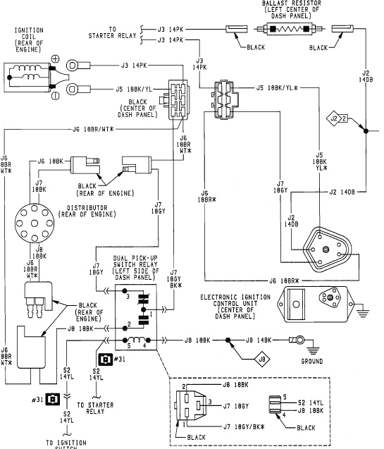
1986 Dodge Ram D150 318 Ignition Coil Wiring Diagram – We will first examine the various types of terminals found on the ignition switch. These terminals are used for the Ignition button, Coil and Accessory. Once we’ve determined the function of the terminals we will be able to recognize the various parts of the ignition wiring. In addition, we will discuss the roles of the Ignition switch, and Coil. The next step is to focus to the accessory terminals.
Ignition switch terminals
An ignition switch contains three separate switches that feed the battery’s current to different locations. The first switch powers the choke. The second switch is responsible for the ON/OFF function of the ignition switch. Different manufacturers use different color codes for various conductors. This is described in a separate article. OMC utilizes this system. The ignition switch also includes a connector for adding the timer.
While many ignition switch terminals may not be authentic, the numbering of the terminals may not match the diagram. Before you plug into the ignition switch ensure that you check the continuity. This can be accomplished using a cheap multimeter. Once you are satisfied with the integrity of the wires you can install the new connector. If your vehicle is equipped with an installed ignition switch the wiring diagram will differ.
It is important to know the differences between the ACC and auxiliary outputs. The ACC, IGN and START terminals are your default connection to the ignition switch. They also function as the main connections to the radio and stereo. The ignition switch is responsible for turning the car’s engine on and off. Older cars have the ignition switch terminals marked “ACC” or “ST” (for individual magnetowires).
Terminals for coil
Understanding the terms is the initial step in finding out what kind of ignition coil you own. The diagram of the basic ignition wiring shows a number different connections and terminals. There are two primary and secondary connections. Each coil is equipped with a distinct operating voltage. To determine what kind of coil you’ve got the first step is to determine the voltage at the S1 primary terminal. S1 should also be checked for resistance in order to identify whether it’s a Type B, B or an A coil.
The chassis’ negative must be connected to the low-tension side. This is the base of the ignition wiring. The high tension part supplies positively directly to the spark plugs. It is essential to suppress the metallic body of the coil is connected to its chassis, however it isn’t essential. The wiring diagram for the ignition will show you how to connect the terminals of either the positive and negative coils. In certain instances scanning the local auto parts store can help you identify defective ignition coils.
The black-and-white-striped wire from the harness goes to the negative terminal. Positive terminal gets the second white wire, which is black in its trace. The black wire connects to the contact breaker. You can examine the connections with a pencil to pull the wires out of the housing. Also, see that the terminals are not bent.
Accessory terminals
Ignition wiring diagrams depict the various wires that are used to power different components. In general, there are four different color-coded terminals for each component. For accessories, red is for starter solenoid, yellow is for battery and blue for accessory. The “IGN” terminal can be used to start the vehicle and control the wipers, as well as other operating functions. This diagram demonstrates how to connect ACC and ST terminals with the rest of the components.
The terminal called BAT is the location where the battery is. Without the battery the electrical system can not begin. A dead battery could make the switch not turn on. A wiring diagram can inform you the location of the battery in your car. The ignition switch is connected to the car’s battery. The BAT terminal is connected to the battery.
Some ignition switches offer an additional “accessory position” that allows users to modify their outputs independent of the ignition. Some customers might want to use the auxiliary input independently of the ignition. For the auxiliary output to be used, wire the connector to the same color as that of the ignition. Then connect it with the ACC end of the switch. Although this is a fantastic option, there’s a thing you need to know. Most ignition switches are set up to show an ACC status when the vehicle is in either the ACC or START positions.
Gallery of 1986 Dodge Ram D150 318 Ignition Coil Wiring Diagram
Gallery of 1986 Dodge Ram D150 318 Ignition Coil Wiring Diagram


