1986 Mazda B2000 Ignition Wiring Diagram – In the beginning, we’ll examine the various types of terminals that are found in the ignition switch. The terminals are the Ignition switch as well as the Coil and the Accessory. Once we know which terminals are used and which ones are not, we can identify the different components of the 1986 Mazda B2000 Ignition Wiring Diagram. We will also talk about the functions and the Coil. Then, we’ll turn our attention to the Accessory terminals.
The terminals of the ignition switch
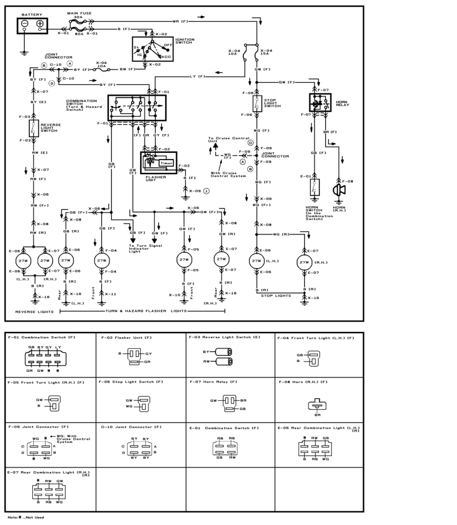
An ignition switch has three switches. They feed the voltage of the battery to many different locations. The first switch powers the choke. The second switch controls the ON/OFF function of the ignition switch. Different manufacturers have different colour-coding systems that correspond to the conductors. OMC uses this method. A tachometer adapter is installed on the ignition switch that allows the installation of an Tachometer.
Although the majority of ignition switch terminals can be duplicated, the number may not be in line with the diagram. Check the continuity of each wire to ensure they are correctly plugged into the ignition switches. This can be checked with a multimeter that is inexpensive. When you’re satisfied with the integrity of your wires, you’ll be able to install the new connector. If your car has an original ignition switch supplied by the factory (or an electrical loom), the wiring loom might differ from that in the car.
The first step is to understand the distinctions between ACC and the auxiliary outputs. The ACC, IGN and START terminals are the default connection to the ignition switch. They are also the main connections to the radio and stereo. The ignition switch is the one that turns the car’s engine to and off. The ignition switch terminals on older vehicles are marked with the letters “ACC” and “ST” (for each magneto wires).
Terminals for coil
The language used to decide the model and type of the ignition coil is the primary thing. You will see several connections and terminals within the basic wiring diagram for ignition that include two primary as well as two secondary. The operating voltage of each coil differs. Therefore, it is essential to first check the voltage at the S1 (primary terminal). S1 should be examined for resistance to determine if the coil belongs to type A, B or C.
The coil’s low-tension end must be connected with the chassis positive. It is also the ground in an ignition wiring diagram. The high-tension side connects the spark plugs to a positive. It is required for the purpose of suppression that the coil’s metallic body be connected to its chassis however, it is not necessary. There are also connections between the positive and negative coil’s terminals on an diagram of the ignition wiring. Sometimes, a defective ignition coil can be identified through a scan performed at an auto repair shop.
The black-and-white-striped wire from the harness goes to the negative terminal. Positive terminal receives the white wire that includes a black trace. The black wire is connected to the contactbreaker. To verify the wires’ connections use a paperclip to remove them off the housing. Make sure you verify that the connections have not been bent.
Accessory terminals
Ignition wiring diagrams depict the various wires utilized to power different components. Each part has four distinct connections that are color coded. Red is used for accessories, yellow is for the battery, while green is the starter solenoid. The “IGN” terminal is used to start the vehicle and control the wipers and other operating features. The diagram illustrates the connection of the ACCas well as ST terminals.
The terminal called BAT is the location where the battery is. The electrical system is not able to begin without the battery. In addition, the switch will not start. The wiring diagram will inform you the location of the battery of your car. The ignition switch and the battery are connected through the accessory terminals. The BAT terminal connects to the battery.
Certain ignition switches have an independent “accessory” position, in which users can manage their outputs without using the ignition. In some cases, users may want to utilize the auxiliary input separately from the ignition. You can use the additional output by connecting it to the ACC terminal on your switch with the same colors. Although this is a great feature, there’s something you need to know. Most ignition switches are set to have an ACC position when the vehicle is in the ACC position, while they’re set to the START position when the car is in the IGN position.
Gallery of 1986 Mazda B2000 Ignition Wiring Diagram
Gallery of 1986 Mazda B2000 Ignition Wiring Diagram


