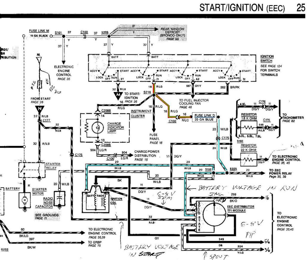
1988 Ford F150 Ignition Switch Wiring Diagram – First, let’s examine the various terminals that are used in the ignition switch. These terminals comprise the Ignition switch as well as the Coil and the Accessory. Once we know the terminals used and which ones are not, we can identify the different components of the 1988 Ford F150 Ignition Switch Wiring Diagram. We’ll also go over the functions for the Ignition switch as well as the Coil. Then, we’ll talk about the functions of the Ignition switch and Coil.
Terminals for the ignition switch
Three switches are found in an ignition switch. Each of these switches feeds the battery’s voltage to various locations. The ON/OFF position of the switch that controls the ignition is managed by the first switch, which delivers power to the choke whenever it’s pulled. Different manufacturers have different color-coding schemes for different conductors. We will cover this in another article. OMC uses this method. A tachometer adapter is installed on the ignition switch to allow for the addition of a tachometer.
Although some ignition switch terminals might not be authentic, the numbering of the terminals may not match the diagram. Examine the integrity of the wires first to ensure that they’re connected correctly to the ignition switch. This can be done with a simple multimeter. After you have verified the integrity of the wires you can then install the connector. If your car has an ignition switch installed the wiring diagram may differ.
It is essential to know the way that ACC outputs and the auxiliary outputs work in order to join them. The ACC/IGN terminals act as the default connections on the ignition switch. The START/IGN connections connect to the stereo or radio. The ignition switch is responsible for turning the car’s engine on and off. The terminals of older vehicles ignition switches are marked by “ACC” and ST (for the individual magneto wires).
Terminals for coil
Understanding the terminology is the initial step in knowing what type of ignition coil you have. The diagram of the basic ignition wiring shows a number different connections and terminals. There are two primary and secondary connections. Each coil operates at a specific voltage. The first step in determining which kind of coil you’re using is to examine the voltage of S1 or the primary terminal. To determine if the coil is an A, C or B coil, you must also test the resistance on S1’s.
The coil with low tension must be connected at the chassis’ minus. This is the ground of the wiring for ignition. The high-tension part connects the spark plugs to a positive. The aluminum body of the coil needs to be linked to the chassis for suppression but isn’t required. It is also possible to see the connections between the positive and the negative coil’s terminals on an ignition wiring diagram. Sometimes, a defective ignition coil is identified by a scan done at an auto repair shop.
The black-and-white-striped wire from the harness goes to the negative terminal. The negative terminal is served by the black trace joined to the white wire. The black wire connects to the contactbreaker. To check the connections between the two wires employ a paperclip to remove them out of the housing. Check that you don’t bend the connectors.
Accessory terminals
The ignition wiring diagrams illustrate the different wires that are used to power the car’s various parts. Typically, there are four different colored terminals for each part. For accessories, red stands the starter solenoid’s color, yellow is for battery and blue for accessory. The “IGN” terminal is used to start the car, operating the wipers and other functions. The diagram illustrates the connection to the ACCand ST terminals.
The battery is connected to the terminal called BAT. The electrical system can’t be started without the battery. The switch won’t be able to turn on if there is no battery there. You can refer to your wiring diagram if you are uncertain about where the car’s batteries are. The accessory terminals of your car connect to the battery and the ignition switch. The BAT Terminal is connected to the battery.
Certain ignition switches come with an accessory setting where users can adjust their outputs and control them without needing to use the ignition. Sometimes, customers may wish to use the auxiliary output separately from the ignition. To allow the auxiliary output to be used, wire the connector in the same color as the ignition. Then , connect it to the ACC end of the switch. This is a useful option, but there’s an important distinction. Most ignition switches are configured to be in an ACC position when the car is in the ACC position, but they’re in the START position when the vehicle is in the IGN position.
Gallery of 1988 Ford F150 Ignition Switch Wiring Diagram
Gallery of 1988 Ford F150 Ignition Switch Wiring Diagram


