1989 Dodge 250 Van 318engine Distributor Ignition Wiring Diagram – First, we will look at the different types of terminals on the ignition switch. They include terminals that are used for Coil, Ignition Switch, and Accessory. Once we’ve established the purpose of the terminals it is possible to determine the various components of the ignition wiring. Then, we will discuss the functions for the Ignition switch and the Coil. Then, we’ll turn our attention to Accessory terminals.
Terminals for ignition switch
The ignition switch consists of three switches. They are the ones that supply the battery’s energy to various locations. The first switch supplies power to the choke when it is pushed. The third is the ignition switch’s ON/OFF position. Different manufacturers have different color-coding schemes for different conductors. We will cover this in another article. OMC follows this procedure. The ignition switch comes with an adapter for the addition of an Tachometer.
While most ignition switch terminals can be duplicated, the numbers might not be consistent with the diagram. Before you plug into the ignition switch ensure that you check the continuity. A multimeter is an excellent tool to check the continuity. After you’re satisfied with the continuity of the wires it is time to connect the new connector. The wiring loom of the ignition switch factory-supplied will be different than the one in your vehicle.
It is essential to know how the ACC outputs and the auxiliary outputs function in order to join them. The ACC and IGN terminals are the default connections for the ignition switch. the START and IGN terminals are the primary connections for the stereo and radio. The ignition switch regulates the engine in your car. Older cars are equipped with ignition switch’s terminals that are labeled “ACC” or “ST” (for individual magnetowires).
Terminals for coil
To identify the kind of ignition coil, the initial step is to understand the terminology. There are a variety of connections and terminals on an ignition wiring schematic which includes two primary and two secondary. The coils are equipped with a particular operating voltage. The initial method of determining what type you’re using is to test the voltage of S1 the main terminal. S1 should also undergo resistance testing to determine if it are a Type A or B coil.
The coil’s low-tension side must be connected with the chassis positive. It is also the ground on an ignition wiring diagram. The high tension side provides positive directly the spark plugs. To prevent noise the coil’s metal body must be connected to the chassis. It’s not necessary to use electricity. The wiring diagram for the ignition will demonstrate how to connect the two terminals of the positive or negative coils. In certain instances it is possible to find an ignition coil that is malfunctioning can be diagnosed with scanning at an auto parts shop.
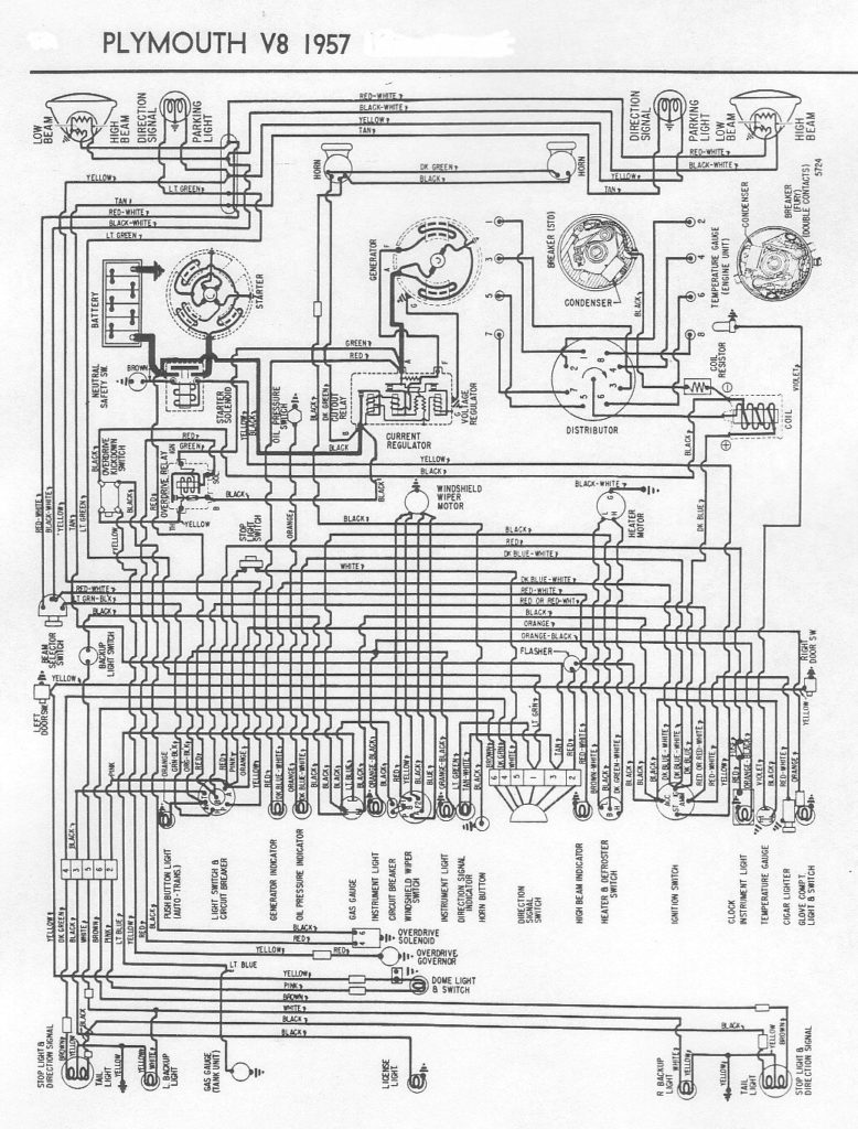
The black-and-white-striped wire from the harness goes to the negative terminal. The terminal that is negative is served by the black trace connected to the white wire. The black wire is connected to the contact breaker. To check the wires’ connections use a paperclip and remove them from the housing. Make sure that the terminals don’t bend.
Accessory terminals
Diagrams of the ignition wiring depict the wiring used to power various parts of the vehicle. There are generally four colored terminals for each component. To identify accessories, red is for starter solenoid, yellow is for battery, and blue is for accessories. The “IGN terminal” is used to provide power to the wipers as well as other operating features. The following diagram shows how to connect both the ACC terminal and ST terminals to other components.
The battery is attached to the terminal named BAT. Without the battery the electrical system will not start. In addition, the switch doesn’t turn on. If you don’t know the location of your car’s battery situated, examine the wiring diagram of your car to determine where it is. The accessory terminals in your car connect to the ignition switch, as well as the battery. The BAT terminal is connected to the battery.
Certain ignition switches provide an additional “accessory position” which allows users to modify their outputs independent of the ignition. Sometimes, customers wish to make use of an auxiliary output that is separate from the ignition. Make use of the additional output by connecting the connector to the ACC terminal on your switch with the same colors. This is a great convenience feature however there’s a distinction. A lot of ignition switches can be set to have an ACC position when the vehicle has been moved into the ACC position. They’ll also be in START mode when the vehicle has moved into the IGN position.
Gallery of 1989 Dodge 250 Van 318engine Distributor Ignition Wiring Diagram
Gallery of 1989 Dodge 250 Van 318engine Distributor Ignition Wiring Diagram


