1989 F250 Ford Ignition System Wiring Diagram – The first step is to take a look at the different types of terminals that are used in the ignition switch. They are terminals that are used for Coil, Ignition Switch, and Accessory. Once we have identified the terminals that are utilized then we can identify the different components of the 1989 F250 Ford Ignition System Wiring Diagram. We’ll also be discussing the functions of the Ignition switch, as well as the Coil. Next, we’ll discuss the roles of the Ignition switch and Coil.
Terminals for ignition switch
An ignition switch has three switches. They feed the battery’s voltage to many different places. The first switch supplies power to the choke whenever it is pushed. The third is the position of the ignition switch’s ON/OFF. Each manufacturer has its unique color-coding system, which we will discuss in another article. OMC follows the same system. The ignition switch comes with a connector for adding the timer.
Although the majority of ignition switch terminals are duplicated, the numbers might not be in line with the diagram. First, check the continuity of all wires to ensure that they are properly plugged into the ignition switches. This can be accomplished using a simple multimeter. Once you’re satisfied with the quality of the connection, you can place the new connector. The wiring loom used for an ignition switch that’s supplied by the factory will be different from the one that you have in your car.
Knowing how the ACC outputs are connected to the other outputs of your car is essential. The ACC and IGN connectors are the default connections of the ignition switch. Although the START, IGN, and ACC terminals are the primary connections for the radio or stereo, the START/IGN terminals are the main ones. The ignition switch regulates the engine in your car. The terminals for the ignition switch on older cars are identified with the alphabets “ACC” as well as “ST” (for the individual magneto wires).
Terminals for coil
Understanding the terminology used is the first step in determining what type of ignition coil. A simple diagram of the wiring will display a range of connections and terminals, including two primary and two secondaries. You need to determine the type of coil you have by testing the voltage on the primary terminal, called S1. S1 must be examined for resistance to identify if the coil is type A, B or C.
The chassis’ negative needs to be connected to the low-tension side. This is also the ground in the ignition wiring diagram. The high-tension component provides the spark plugs with positive. The coil’s metal body needs to connect to the chassis to suppress the effect but is not electrically necessary. The diagram of the ignition wiring will also reveal the connection of the negative and positive coil terminals. Sometimes, an inspection at an auto parts store could detect a defective ignition wire.
The black-and-white-striped wire from the harness goes to the negative terminal. The positive terminal is connected to the white wire with the black trace. The black wire goes to the contact breaker. You can examine the connections with a pencil to pull the wires out of the housing. Make sure you don’t bend the connectors.
Accessory Terminals

Diagrams of ignition wiring show the various wires utilized for powering the various components. Typically there are four distinct colors-coded terminals that are used for each component. Red stands for accessories, yellow represents the battery and green for the solenoid for starters. The “IGN” terminal can be used to start the car, operate the wipers, as well as other features. The diagram shows the connection between the ACC- and ST terminals.
The battery is connected to the terminal called BAT. Without the battery the electrical system can not get started. The switch won’t turn off if the battery isn’t there. If you’re not sure of the exact location where the battery in your car is situated, look at the wiring diagram of your car to determine the best way to find it. The ignition switch and battery are connected through the accessory terminals. The BAT Terminal is connected to the battery.
Some ignition switches feature an independent “accessory” position, in which users can control their outputs with no ignition. Sometimes, users want to utilize an additional output that is not connected to the ignition. The auxiliary output can be utilized by wiring the connector with the same colors as your ignition and connecting it to the ACC terminal of the switch. This is a useful option, but there’s one important distinction. The majority of ignition switches have an ACC position when the vehicle is in the ACC however they’ll be in the START position when the vehicle is in IGN.
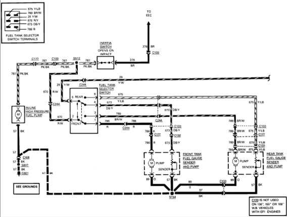
Gallery of 1989 F250 Ford Ignition System Wiring Diagram
Gallery of 1989 F250 Ford Ignition System Wiring Diagram


