1989 Ford F150 Ignition Wiring Diagram – First, let’s examine the various terminals used on the ignition switch. They include terminals for the Ignition switch, Coil, and Accessory. After we’ve identified which terminals are used, we can begin to identify the different components of the 1989 Ford F150 Ignition Wiring Diagram. We will also discuss the functions for the Ignition switch as well as the Coil. Then, we’ll talk about the roles of the Ignition switch and Coil.
Terminals for ignition switch
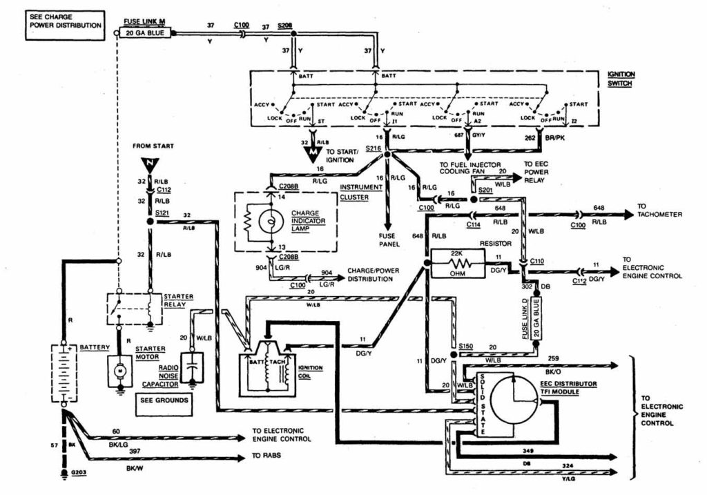
Three switches can be found in an ignition switch. Each of these three switches is able to feed the battery’s voltage to various places. The ON/OFF position of the switch that controls the ignition is managed by the third switch, which delivers power to the choke whenever it is pushed. Each manufacturer has their own color-coding system, which we will discuss in another article. OMC uses this method. The ignition switch comes with an adapter for the addition of the tachometer.
Even though most ignition switch terminals do not have an original number, they may have a different one. Verify the continuity of the wires first to ensure that they’re connected correctly to the ignition switch. A multimeter is a good instrument to verify the continuity. Once you’re satisfied with the connection it’s time to connect the new connector. If your car has an installed ignition switch the wiring diagram will differ.
Knowing how the ACC outputs connect to the other outputs of your car is essential. The ACC and IGN connectors are the default connections of the ignition switch. The START, IGN, and ACC terminals are primary connections to the radio or stereo, the START/IGN terminals are the most important ones. The ignition switch switches the car’s engine ON and off. Older vehicles have ignition switch’s terminals that are labeled “ACC” or “ST” (for individual magnetowires).
Terminals for coil
The first step to determine the type of ignition coil is to understand the terminology employed. A basic ignition wiring diagram will show a variety of terminals and connections, which include two primary terminals and two secondary. You need to determine the type of coil that you have by testing the voltage on the primary terminal, S1. To determine if it is an A, C or B coil it is recommended to also test S1’s resistance.
The low-tension coil side must be connected at the chassis’ less. This is the ground on the wiring diagram for ignition. The high tension side provides positively directly to the spark plugs. The aluminum body of the coil needs to be linked to the chassis for suppression, but it isn’t electrically required. The ignition wiring diagram will also demonstrate how to connect the negative and positive coil’s terminals. In some cases, you’ll find that the ignition coil is damaged and is easily identified with a scan at an auto parts shop.
The black-and-white-striped wire from the harness goes to the negative terminal. The white wire has a black color and goes to the negative terminal. The black wire is connected to the contactbreaker. If you’re not sure about the connections between the twowires, use the clip of a paperclip to remove them from the housing of the plug. Check that the terminals aren’t bent.
Accessory terminals
The wiring diagrams of the ignition illustrate the different wires that provide power to the various parts of the vehicle. There are typically four colors of terminals connected to each part. Red is for accessories, yellow is for the battery, while green is the starter solenoid. The “IGN terminal” is used to run the wipers, and other operating features. The diagram shows the connection of the ACC- and ST terminals.
The terminal BAT is the connection for the battery. Without the battery, the electrical system does not get started. Furthermore the switch won’t come on. You can refer to your wiring diagram if not sure where the batteries of your car are. The ignition switch is connected to the car’s battery. The BAT terminal is connected with the battery.
Certain ignition switches come with an additional position in which users can alter their outputs and manage them without the need to use the ignition. Sometimes, customers wish to make use of the auxiliary output separately from the ignition. To make use of the auxiliary output, connect the connector using the same colors as the ignition connecting it to the ACC terminal on the switch. Although this is a great feature, there’s one thing you need to know. Most ignition switches are configured to display an ACC status when the car’s at either the ACC or START position.
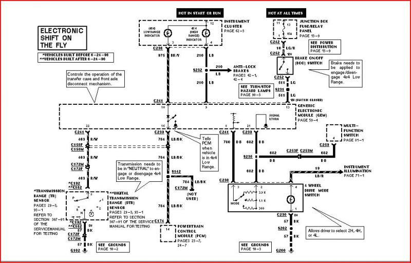
Gallery of 1989 Ford F150 Ignition Wiring Diagram
Gallery of 1989 Ford F150 Ignition Wiring Diagram


