1989 Omc Cobra Ignition Wiring Diagram – We will first examine the different types of terminals for the ignition switch. They include terminals for the Ignition switch, Coil, and Accessory. Once we understand the function of each kind of terminal, we can then determine the components of the ignition wiring. We’ll also go over the roles of the Ignition switch and Coil. Then we’ll move on to the Accessory Terminals.
Terminals for ignition switch

An ignition switch is composed of three different switches. These are responsible for feeding the battery’s power to several places. The choke is powered by the first switch. The second switch is responsible for the ON/OFF switch of the ignition switch. Different manufacturers use different color-coding systems that correspond to the conductors. OMC utilizes this system. Connectors can be attached to the ignition switch to add the digital Tachometer.
While the majority of ignition switch terminals don’t have the original design, the numbering may not match that of the diagram. You should first check the integrity of the wires to ensure that they are connected to the ignition switch in the correct way. You can do this with a simple multimeter. After you’re sure that all wires are running in good harmony, you can attach the new connector. If your car has an ignition switch installed the wiring diagram may differ.
Understanding how the ACC outputs are connected to the auxiliary outputs of your vehicle is crucial. The ACC and IGN terminals are the default connection on your ignition switch. the START and IGN terminals are the principal connections for radio and stereo. The ignition switch switches the car’s engine on and off. The terminals of the ignition switch on older cars are labeled with the letters “ACC” and “ST” (for individual magneto wires).
Terminals for coil
Understanding the terminology is the initial step to knowing what type of ignition coil you’ve got. The basic ignition wiring diagram shows a number different connections and terminals. There are two primary and one secondary. The coils are equipped with a particular operating voltage. The initial method of determining what type you have will involve testing the voltage of S1 the primary terminal. To determine if the coil is a Type A, C or B coil it is recommended to also test the resistance on S1’s.
The coil’s low-tension end must be connected to the chassis positive. This is also the ground on the diagram of the ignition wiring. The high-tension side is a positive connection to the sparkplugs. The coil’s aluminum body needs to be connected to the chassis for suppression but isn’t required. The ignition wiring diagram will also reveal the connections between the negative and positive coil’s terminals. You may find an issue with the ignition coil that can be easily diagnosed by scanning it at the auto parts shop.
The black-and-white-striped wire from the harness goes to the negative terminal. The negative terminal is served by the black trace that’s attached to the white wire. The black wire goes to the contact breaker. It is possible to remove the black wire from the plug housing using a paper clip if you are unsure about the connection. Be sure to check that the terminals haven’t been bent.
Accessory Terminals
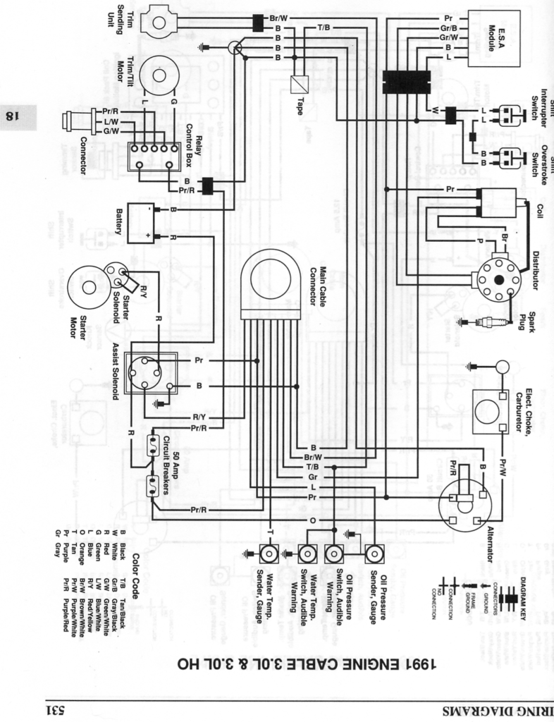
Diagrams of ignition wiring show the various wires that are used to power different components. Typically, there are four different color-coded terminals for each component. Red is used for accessories while yellow is the battery, while green is for the solenoid for starters. The “IGN” terminal can be used to start the car , and also to operate the wipers, as well as other operating functions. The diagram illustrates how you can connect ACC or ST terminals, and other.
The battery is connected to the terminal called BAT. The electrical system won’t start in the event that the battery isn’t connected. Also, the switch won’t be able to turn on without the battery. It is possible to refer to your wiring diagram if unsure where your car’s batteries are. The ignition switch as well as the battery are connected through the accessory terminals. The BAT connector is connected to the battery.
Some ignition switches come with an additional position. It allows users to access their outputs from a different location without having to turn on the ignition. Some customers might want to use the auxiliary input independently of the ignition. You can use the auxiliary output by connecting it to an ACC terminal on your switch with the same colors. This is a useful feature, however there’s one important difference. Most ignition switches are configured to display an ACC status when the car’s at either the ACC or START positions.
Gallery of 1989 Omc Cobra Ignition Wiring Diagram
Gallery of 1989 Omc Cobra Ignition Wiring Diagram


