1989 Softail Ignition Switch Wiring Diagram – The first step is to look at the various types of terminals for the ignition switch. These include the terminals that are for the Ignition switch, Coil, and Accessory. Once we’ve determined the function of the terminals we will be able to determine the various components of the ignition wiring. We will also discuss the roles of the Ignition switch as well as the Coil. Then, we will focus on the accessory terminals.
The terminals of the ignition switch
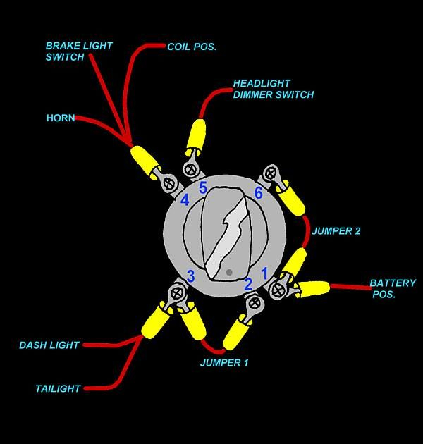
Three switches can be found on an ignition switch. Each of these switches transmits the battery’s current to several different destinations. The first switch provides power to the choke when it is pushed. The third is the ignition switch’s ON/OFF position. Each manufacturer has its individual color-coding system that we will discuss in another article. OMC follows this system. The ignition switch comes with an adapter for the addition of the tachometer.
While the majority of ignition switch terminals don’t appear in their original configuration however, the numbers may not be in line with the diagram. Verify the continuity of the wires first to ensure that they’re connected correctly to the ignition switch. This can be accomplished using a cheap multimeter. When you are satisfied with the continuity of the wires, you can connect the new connector. The wiring loom of a factory-supplied ignition system switch is distinct.
Understanding how the ACC outputs are connected to the other outputs in your car is essential. The ACC and IGN terminals are the default connections on your ignition switch. the START and IGN terminals are the main connections to the radio and stereo. The ignition switch switches the car’s engine on and off. The terminals for the ignition switch on older cars are labeled with the initials “ACC” and “ST” (for individual magneto wires).
Coil terminals
The first step in determining the kind of ignition coil is to comprehend the terms employed. The basic ignition wiring diagram depicts various connections and terminals. There are two primary and secondary connections. The coils have a specific operating voltage. The initial step to determine which one you’ve got is to check the voltage at S1, the primary terminal. S1 must be tested for resistance in order to identify if the coil is type A, B or C.
The chassis’ negative must be connected to the side of low-tension. This is also the ground in the diagram of ignition wiring. The high-tension component supplies positive directly to the spark plugs. The coil’s metal body needs to connect to the chassis to suppress the effect but is not electrically essential. A wiring diagram can depict the connection between positive and negative coil terminals. In certain instances, you’ll find that the ignition coil is damaged and is easily identified with a scan in an auto parts store.
The black-and-white-striped wire from the harness goes to the negative terminal. The terminal for the negative is served by the trace in black that’s attached to the white wire. The black wire goes to the contact breaker. If you’re not sure about the connections of the two, try using a paper clip to remove them from the housing of the plug. It is also important to ensure that the terminals don’t bend.
Accessory Terminals
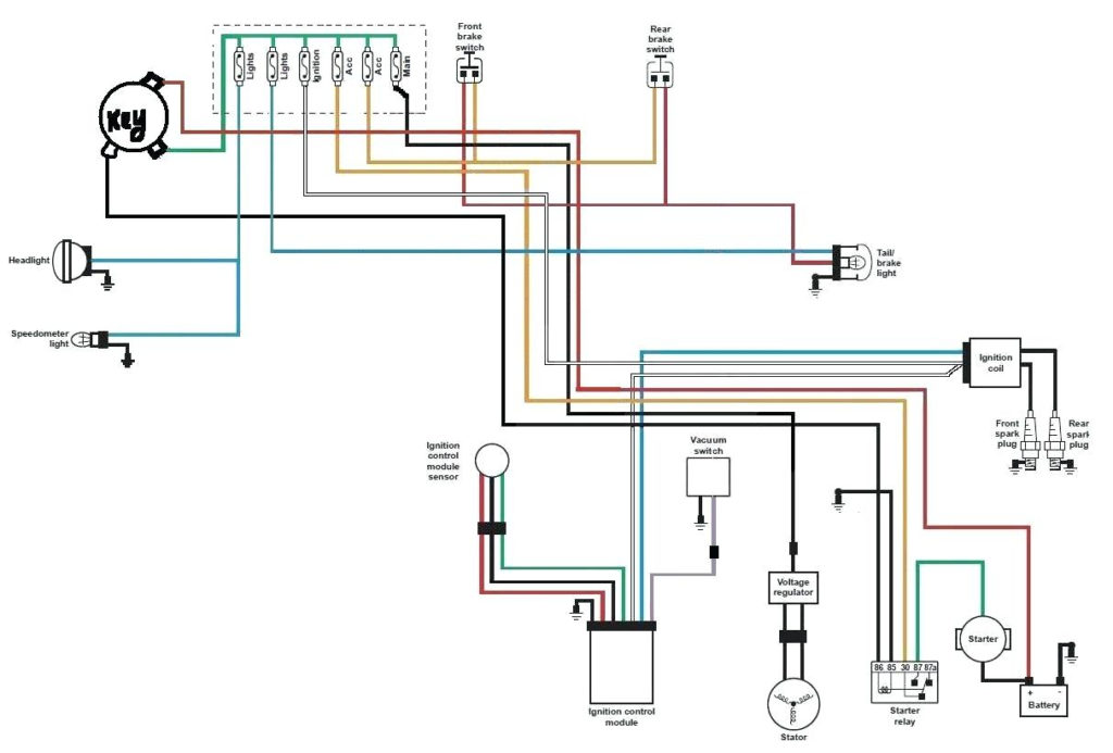
Diagrams of ignition wiring show the various wires used to power the car’s various parts. There are typically four color-coded terminals to each component. Accessories are red and the battery yellow the starter solenoid is green. The “IGN terminal is used to start the vehicle, controlling the wipers and other functions. This diagram shows how you can connect ACC and ST terminals with the other components.
The terminal BAT is where the battery is. The electrical system will not start without the battery. A dead battery could cause the switch to stop turning on. To find the battery in your car look over your wiring diagram. The ignition switch and battery are connected via accessory terminals. The BAT connector connects to your battery.
Certain ignition switches have an accessory setting where users can adjust their outputs as well as control them without the need to use the ignition. Customers sometimes want an auxiliary output that can be used separately from the ignition. You can use the additional input by connecting the connector to the ACC terminal. This is an excellent feature, however there’s an important distinction. The majority of ignition switches are designed to display an ACC status when the vehicle is at either the ACC or START positions.
Gallery of 1989 Softail Ignition Switch Wiring Diagram
Gallery of 1989 Softail Ignition Switch Wiring Diagram


