1990 Ford F250 Ignition Wiring Diagram – The first step is to take a look at the different kinds of terminals for the ignition switch. These include the terminals that are for the Ignition switch, Coil, and Accessory. Once we know the purpose of these terminals then we can determine the various components in the ignition wiring. Then, we will discuss the roles of the Ignition switch, as well as the Coil. After that, we’ll turn our attention to the Accessory terminals.
Terminals for ignition switches
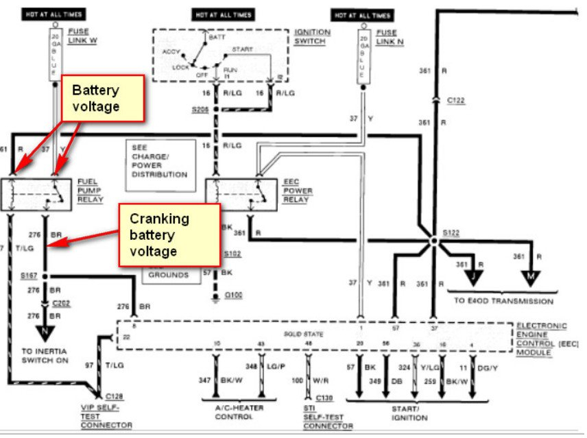
An ignition switch is comprised of three switches. They supply the voltage of the battery to many different locations. The first switch supplies power to the choke whenever it is pushed. The second is the ignition switch’s ON/OFF position. Different manufacturers have distinct color-coding systems that correspond to the conductors. OMC utilizes this method. A connector can be added to the ignition switch to include an electronic tachometer.
While the majority of the ignition switch terminals aren’t authentic, the numbering of each might not be consistent with the diagram. Before plugging into the ignition switch, make sure to check the continuity. This can be checked using a cheap multimeter. After you’re happy with the continuity of the wires, connect the new connector. The wiring loom used in an ignition system switch that is supplied by the manufacturer is distinct.
It is essential to know how the ACC outputs and auxiliary outputs function in order to join them. The ACC and IGN connectors are the standard connections of the ignition switch. The START, IGN, and ACC terminals are the primary connections for radios or stereo, the START/IGN connections are the most important ones. The ignition switch is responsible for turning the car’s engine on and off. Older cars are equipped with ignition switch’s terminals that are labeled “ACC” or “ST” (for individual magnetowires).
Terminals for coil
Understanding the terminology is the initial step towards knowing what type of ignition coil you own. In a simple ignition wiring diagram, you will see several different connections and terminals, which include two primary and two secondary. Each coil has a specific operating voltage. To determine what kind of coil you’ve got the first step is to check the voltage at S1, which is the primary terminal. To determine if the coil is an A, C or B coil, you should also check the resistance of S1.
The low-tension end of the coil needs to be connected to the chassis”negative. This is also the ground for an ignition wiring diagram. The high-tension side delivers the positive power directly to the spark plugs. The aluminum body of the coil has to be linked to the chassis to prevent it from being smothered, but it isn’t electrically required. The wiring diagram for ignition will also outline the connection of the positive coil terminals. Sometimes, a defective ignition coil can be identified by a scan done at an auto repair shop.
The black-and-white-striped wire from the harness goes to the negative terminal. The positive terminal also gets the white wire that has a black trace. The black wire is connected to the contact breaker. To verify the connections between the two wires, employ a paperclip to remove them out of the housing. It is also important to ensure that the terminals do not bend.
Accessory terminals

Diagrams of the ignition wiring show the wires used to supply power to different parts of the car. There are generally four colors-coded terminus of each part. The red color is used for accessories and yellow is for the battery, and green is for the solenoid for starters. The “IGN” terminal allows you to start the car, control the wipers, or any other operation features. The diagram illustrates how you can connect ACC or ST terminals as well as the rest.
The terminal BAT connects the battery to the charger. The electrical system won’t start in the event that the battery isn’t connected. Additionally the switch isn’t turned on. You can view your wiring diagram to determine the location of your car’s batteries. located. The accessory terminals in your car connect to the battery as well as the ignition switch. The BAT terminal is connected to the battery.
Some ignition switches are equipped with an additional position. This lets users connect their outputs to a different location without the ignition. Sometimes, customers want to use the auxiliary output separately from the ignition. The auxiliary output is used to connect the connector with the same colors as the ignition, and then attaching it to the ACC terminal of the switch. Although this is a great option, there’s a thing to be aware of. Most ignition switches will have an ACC position when the vehicle is in the ACC however, they will be at the START position if the vehicle is in IGN.
Gallery of 1990 Ford F250 Ignition Wiring Diagram
Gallery of 1990 Ford F250 Ignition Wiring Diagram


