1990 Gmc Sierra Ignition Wiring Diagram – We will first look at the various kinds and functions of terminals found on the ignition switches. These are the terminals used that are used for Coil, Ignition Switch, and Accessory. Once we’ve established the purpose of the terminals it is possible to recognize the various parts of the ignition wiring. We will also discuss what functions are available for the Ignition switch and the Coil. We will then discuss the roles of the ignition switch and Coil.
Terminals for ignition switches
An ignition switch contains three switches that supply the battery’s power to various destinations. The first switch supplies power to the choke, and the third switch toggles the on/off state of the switch. Different manufacturers use different colors for various conductors. This is explained in a separate article. OMC follows this method. The ignition switch comes with an option to connect an tachometer.
While most ignition switch terminals may not be original, the numbering for each might not be consistent with the diagram. First, check the continuity of all wires to ensure that they are properly connected to the ignition switches. You can check this using a simple multimeter. After you’ve confirmed that the wires are in good condition, you can then connect the connector. If your car has an original factory-supplied ignition switch (or an electrical loom), the wiring loom will differ from that in your vehicle.
The first step is to understand the distinctions between ACC and the auxiliary outputs. The ACC and IGN terminals are the default connection on your ignition switch, and the START and IGN terminals are the primary connections to the radio and stereo. The ignition switch is the engine’s switch to turn off or on. The terminals for the ignition switch on older cars are identified with the letters “ACC” and “ST” (for the individual magneto wires).
Terminals for coil
The language used to decide the kind and model of an ignition coil is the primary thing. A basic ignition wiring diagram will show a variety of connections and terminals, including two primary and two secondaries. The coils are equipped with a particular operating voltage. The initial method of determining what type you have will involve testing the voltage on S1, the main terminal. S1 must be tested for resistance in order to determine if the coil is type A, B and/or C.
The low-tension coil side must be connected to the chassis’s less. This is also the ground in an ignition wiring diagram. The high-tension side supplies positive direct to the sparkplugs. To reduce the noise the body of the coil must be connected to the chassis. But, it’s not necessary to electrically connect. There are also connections of the positive and the negative coil’s terminals on an ignition wiring diagram. Sometimes, a damaged ignition coil is identified with a scan in an auto parts shop.
The black-and-white-striped wire from the harness goes to the negative terminal. The positive terminal is connected to the white wire with an black trace. The black wire is connected to the contactbreaker. You can check the connections with a pencil to pull the wires out from the housing. Be sure the terminals aren’t bent.
Accessory terminals
Diagrams of the ignition wiring depict the wires that power various parts of the vehicle. Typically, there are four different color-coded terminals for each component. The red color represents accessories, yellow represents the battery and green is for the solenoid for starters. The “IGN” terminal is used to turn on the car, operate the wipers and other features. This diagram shows how you can connect ACC and ST terminals with the other components.
The battery is attached to the terminal whose name is BAT. Without the battery, the electrical system does not start. The switch will not turn off if the battery isn’t there. If you don’t know the exact location where the battery in your car is situated, you can look at your wiring diagram to see where it is. The accessory terminals in your car are connected with the battery and ignition button. The BAT connector connects to your battery.
Some ignition switches are equipped with an additional position. This lets users access their outputs from a different place without the ignition. Sometimes, customers want to use the auxiliary output separate from the ignition. You can use the auxiliary output by connecting the connector to the ACC terminal on the switch with the same colors. While this is an excellent option, there’s an important difference. Most ignition switches will have an ACC position if the car is in the ACC, but they will be in the START position if the vehicle is in IGN.
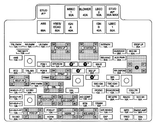
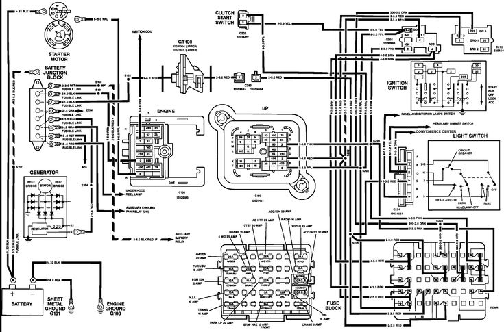
Gallery of 1990 Gmc Sierra Ignition Wiring Diagram
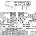
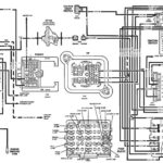
Gallery of 1990 Gmc Sierra Ignition Wiring Diagram


