1991 Ford F150 Ignition Wiring Diagram – In the beginning, we’ll take a look at the various kinds of terminals that are found on the ignition switch. These terminals include the Ignition switch, the Coil and the Accessory. Once we understand the function of each kind of terminal, it is possible to identify the parts of the ignition wiring. In addition, we will discuss the functions of the Ignition switch and Coil. Then, we’ll focus on the accessory terminals.
Terminals for ignition switches
An ignition switch has three switches. They feed the voltage of the battery to many different locations. The first switch provides the choke with power when it is pushed. The third is the position of the ignition switch’s ON/OFF. Different manufacturers use different colors for various conductors. This is explained in another article. OMC utilizes this method. This connector allows the attachment of a speedometer the ignition switch.
Even though most ignition switch terminals do not have an original number, they might have a different number. Before you plug in the ignition switch, make sure to check the continuity. A multimeter that is inexpensive can help you do this. After you have verified the continuity of the wires you are able to connect the connector. If you’re using a factory-supplied ignition switch the wiring loom will be different from the one you have in your car.
Before you can connect the ACC outputs to the auxiliary outputs of your car, it is important to know the fundamentals of these connections. The ACC, IGN and START terminals are the primary connections to the ignition switch. They are also the primary connections to your radio and stereo. The ignition switch switches the car’s engine on and off. The terminals of older cars ignition switches are marked by “ACC” as well as ST (for specific magneto wires).
Terminals for coil
Understanding the terminology is the initial step to finding out what kind of ignition coil you own. An ignition wiring diagram will reveal a variety of terminals and connections including two primary and two secondary. You must determine the type of coil you are using by testing the voltage on the primary terminal, S1. S1 must also be inspected for resistance to determine whether it’s a Type B, B or an A coil.
The low-tension coil side must be connected to the chassis’ plus. This is also the ground in the wiring diagram for ignition. The high-tension end supplies positive direct to the sparkplugs. To reduce the noise, the coil’s metal body is required to be connected to the chassis. It is not necessary to electrically connect. The diagram of the ignition wiring will also indicate how to connect the positive coil terminals. Sometimes, a check at an auto parts shop can diagnose a malfunctioning ignition wire.
The black-and-white-striped wire from the harness goes to the negative terminal. The white wire is black-colored and goes to the negative terminal. The black wire connects with the contact breaker. To verify the connections, employ a paperclip, or a pencil to remove them of the housing for the plug. Make sure that the terminals do not bend.
Accessory terminals
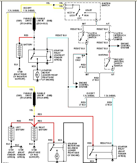
Diagrams of the ignition wiring show the wiring used to provide power to various components of the car. Each part has four distinct colored connections. Red is used for accessories and yellow is for the battery, and green is for the solenoid for starters. The “IGN” terminal is used to turn on the car, turn on the wipers, and other features. The diagram demonstrates how to connect the ACC and ST terminals to the other components.
The terminal called BAT is where the battery is connected. The electrical system will not start without the battery. Furthermore the switch won’t come on. To locate your car’s battery examine the wiring diagram. The accessory terminals in your car are connected to the battery and ignition button. The BAT Terminal is connected to the Battery.
Some ignition switches come with the option of an “accessory position” that lets users adjust their outputs independently of the ignition. Sometimes, customers want to make use of an additional output independent of the ignition. Make use of the additional output by connecting the connector to an ACC terminal on the switch using the same colors. Although this is a fantastic option, there’s a thing you need to know. The majority of ignition switches have an ACC position if the car is in ACC however, they’ll be in the START position if the car is in IGN.
Gallery of 1991 Ford F150 Ignition Wiring Diagram
Gallery of 1991 Ford F150 Ignition Wiring Diagram


