1991 Honda Civic Ignition Switch Wiring Diagram – The first step is to examine the different types of terminals that are used on the ignition switch. These terminals serve for the Ignition button, Coil and Accessory. When we have a clear understanding of the purpose of each kind of terminal, we are able to identify the various components of the ignition wiring. We’ll also go over the functions of the Ignition switch and Coil. We will then turn our attention towards the accessory terminals.
Terminals for the ignition switch
An ignition switch has three switches that supply the battery’s current to various destinations. The ON/OFF setting of the switch that controls the ignition is managed by the third switch, which supplies the choke with power when it’s pushed. Different manufacturers have different color codes for various conductors. This is discussed in another article. OMC utilizes this system. There is a connector inside the ignition switch to allow attaching the tachometer.
While the majority of the ignition switch terminals may not be authentic, the numbering of each might not be consistent with the diagram. Before you plug in the ignition switch, be sure to test the continuity. This can be done with a simple multimeter. After you’re satisfied with the quality of the connection, you can place the new connector. If you’re using an ignition switch that is supplied by the manufacturer, the wiring loom is different from that you have in your car.
You must first understand how the ACC outputs and the auxiliary outputs function to join them. The ACC terminals as well as the IGN terminals function as the primary connections to the ignition switch. The START and IGN connections are the main connections for radio and stereo. The ignition switch operates the engine’s off/on button. On older cars the terminals of the ignition switch are identified with the alphabets “ACC”, and “ST” (for the individual magnetic wires).
Terminals for coil
The terms used to define the type and model of an ignition coil is the primary thing. The basic ignition wiring diagram depicts various connections and terminals. There are two primary and secondary connections. You need to determine the type of coil that you own by examining the voltage at the primary terminal S1. Also, you should check S1 for resistance to determine whether it is an A, B, or C coil.
The coil’s low-tension side must be connected to the chassis positive. This is the ground of the wiring for ignition. The high-tension supply supplies positively directly to spark plugs. For suppression purposes the body of the coil must be connected to chassis. However, it is not necessary to connect the coil electrically. A wiring diagram can also depict the connection between positive and negative coils. In certain cases, a scan at your local auto parts shop will help identify malfunctioning ignition coils.
The black-and-white-striped wire from the harness goes to the negative terminal. The terminal that is negative is served by the black trace attached to the white wire. The black wire is connected to the contact breaker. To check the connection, use a paperclip or a pencil to pull them out of the plug housing. Make sure that the connectors don’t bend.
Accessory terminals
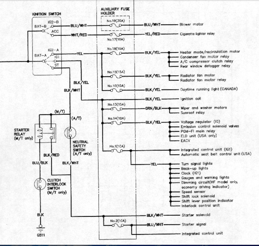
The ignition wiring diagrams illustrate the various wires utilized to power the vehicle’s various parts. There are typically four colored terminals for each component. The accessories are red while the battery is yellow the starter solenoid green. The “IGN” terminal can be used to start the car and operate the wipers as well as other operational functions. The diagram illustrates the connection of the ACCas well as ST terminals.
The terminal referred to as BAT is the place where the battery is. Without the battery the electrical system will not get started. The switch won’t turn off if the battery isn’t there. A wiring diagram can tell the location of the battery of your car. The ignition switch is connected to the car’s battery. The BAT Terminal is connected to the battery.
Some ignition switches are equipped with an additional position. This allows users to connect their outputs to another location without having to turn on the ignition. Some customers want an auxiliary output that can be used independently from the ignition. To use the additional output, wire the connector with the same colors as the ignition connecting it to the ACC terminal on the switch. This feature is convenient however it does have one major distinction. Most ignition switches are configured to be in an ACC position when the vehicle is in the ACC position, while they’re in the START position when the car is in the IGN position.
Gallery of 1991 Honda Civic Ignition Switch Wiring Diagram
Gallery of 1991 Honda Civic Ignition Switch Wiring Diagram


