1992 Dodge Dakota Ignition Wiring Diagram – Let’s first examine the different kinds and functions of terminals found in the ignition switches. These are the terminals for the Ignition, Coil, or Accessory. After we’ve identified the purpose of the terminals we can identify the various parts of the ignition wiring. In addition, we will discuss the function of the Ignition switch and Coil. Then, we will concentrate on the accessories terminals.
Terminals for ignition switch
There are three separate switches in the ignition switch, and they transmit the battery’s current voltage to various places. The first switch provides power to the choke when it is pushed. The second is the position of the ignition switch’s ON/OFF. Different manufacturers use different colors for various conductors. This is described in a separate article. OMC utilizes this approach. Connectors can be connected to the ignition switch to add an electronic Tachometer.
Even though most ignition switch terminals don’t carry an original number, they might have a different number. Check the electrical continuity to see if they are plugged into the correct ignition switch. This can be checked using a simple multimeter. After you’ve confirmed the continuity of the wires you can then install the connector. The wiring loom used for an ignition switch that is supplied by the manufacturer will differ from the one in your vehicle.
To connect the ACC outputs to the auxiliary outputs on your car, you need to first understand how these two connections work. The ACC and IGN terminals are the default connections for your ignition switch. the START and IGN terminals are the primary connections for stereo and radio. The ignition switch’s function is to turn the car’s engines on and off. On older cars the ignition switch’s terminals are marked with the letters “ACC” and “ST” (for distinct magnetic wires).
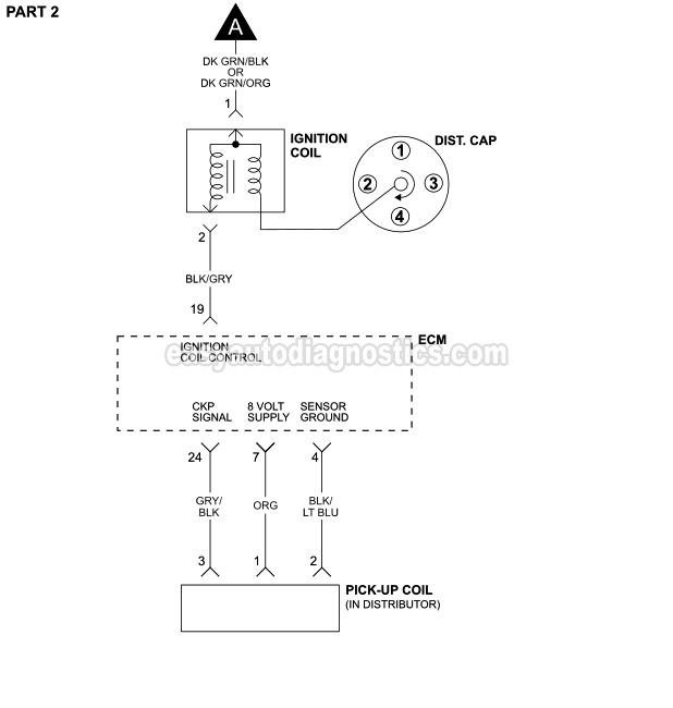
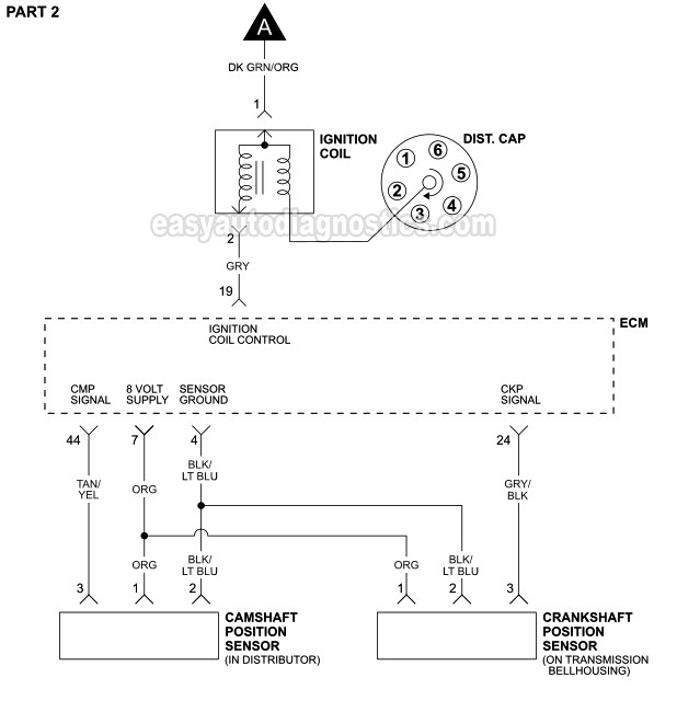
Terminals for coil
The first step to determine the kind of ignition coil is to understand the terms employed. You’ll see a number of connections and terminals in an ignition wiring schematic that include two primary and two secondary. Each coil has an operating voltage. The first step to determine the kind you have is to check the voltage at S1 or the primary terminal. To determine if the coil is an A, C, or B coil it is recommended to also test the resistance on S1’s.
The coil’s low-tension end must be connected to the chassis positively. This is also the ground on the wiring diagram for ignition. The high-tension end is a positive connection to the sparkplugs. To reduce the noise, the coil’s body metal must be connected to the chassis. This is not necessary for electrical use. The wiring diagram will also show the connection between the positive and negative coil terminals. In certain cases scanning your local auto parts shop will be able to diagnose the malfunctioning ignition coils.
The black-and-white-striped wire from the harness goes to the negative terminal. The positive terminal also gets the second white wire, which is black in its trace. The black wire connects to the contact breaker. If you’re not sure about the connections of the twowires, use a paper clip to remove them from the housing of the plug. Be sure the terminals aren’t bent.
Accessory terminals
Diagrams of ignition wiring show the various wires that are used for powering the various components. There are generally four colored terminals for each component. The accessories are red while the battery is yellow the starter solenoid is green. The “IGN terminal is used for starting the car, controlling the wipers, and for other functions. This diagram shows how you can connect ACC and ST terminals to the rest of the components.
The terminal BAT is the connection for the battery. The electrical system won’t start in the event that the battery isn’t connected. Also, the switch won’t start without the battery. You can refer to your wiring diagram if you are unsure where your car’s batteries are. The accessory terminals of your car are connected to the ignition switch and the battery. The BAT terminal is connected with the battery.
Some ignition switches include an additional position in which users can adjust their outputs and control them without the need to use the ignition. Some customers might want to use the auxiliary input independently of the ignition. The auxiliary output can be used by wiring the connector with the same color as your ignition, and then attaching it to the ACC terminal of the switch. While this is a convenient feature, there is one crucial distinction. Most ignition switches will have an ACC position when the vehicle is in ACC, but they’ll be in the START position when the car is in IGN.
Gallery of 1992 Dodge Dakota Ignition Wiring Diagram
Gallery of 1992 Dodge Dakota Ignition Wiring Diagram


