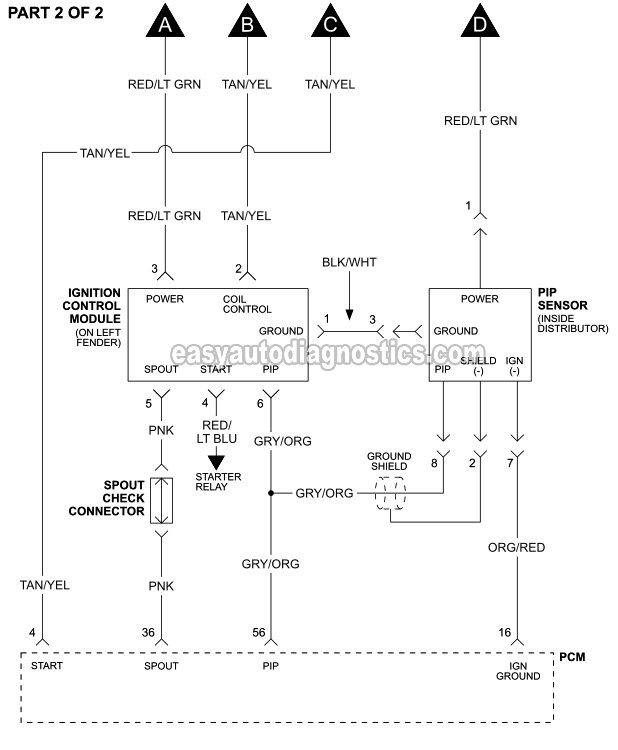
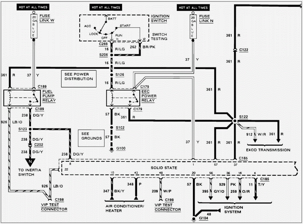
1992 Ford F150 Ignition Wiring Diagram – In the beginning, we’ll take a look at the various kinds of terminals that are found in the ignition switch. They include terminals for the Ignition switch, Coil, and Accessory. Once we have identified what these terminals are and what they do, we can then determine the various components in the ignition wiring. In addition, we will discuss the roles of both the Ignition Switch and Coil. Then we’ll discuss the Accessory Terminals.
Terminals for ignition switch
There are three switches on an ignition switch that feed the battery’s voltage to various places. The first one supplies the choke with power when it is pushed. The third is the switch that controls the ignition’s ON/OFF positions. Different manufacturers have different color-coding schemes for different conductors. We’ll discuss this in a separate article. OMC utilizes this system. An adapter is included on the ignition switch to allow the addition of the Tachometer.
While many ignition switch terminals don’t appear in their original configuration however, the numbers may not be in line with the diagram. Check the continuity of all wires to ensure they are correctly plugged into the ignition switches. This can be accomplished using an inexpensive multimeter. Once you are satisfied that all wires are in good order, you can attach the new connector. The wiring loom used in an ignition system switch that is supplied by the manufacturer is different.
For connecting the ACC outputs to the auxiliary outputs on your vehicle, you have to first understand how these two connections work. The ACC and IGN terminals are the default connections for your ignition switch, and the START and IGN terminals are the main connections for the radio and stereo. The ignition switch is the engine’s switch to turn off or on. On older cars, the ignition switch terminals are marked with the initials “ACC” and “ST” (for distinct magnetic wires).
Terminals for coil
The terms used to define the kind and model of the ignition coil is the most important thing. An ignition wiring diagram will show a variety of terminals and connections comprising two primary and two secondaries. Each coil comes with its own operating voltage. To determine what kind of coil you have the first step is to check the voltage at S1, the primary terminal. To determine if it is a Type A, C or B coil it is recommended to also test S1’s resistance.
The coil with low tension must be connected to the chassis’ minus. It is also the ground for the diagram of ignition wiring. The high-tension component supplies the spark plugs with positive. For suppression purposes the body of the coil must be connected to chassis. However, it is not required to connect electrically. The wiring diagram of the ignition will show you how to connect the two terminals of the positive and negative coils. You may find an issue with your ignition coil that can be easily diagnosed by scanning it at an auto parts retailer.
The black-and-white-striped wire from the harness goes to the negative terminal. The positive terminal also receives the white wire that is black in its trace. The black wire is connected to the contact breaker. It is possible to remove the black wire from the plug housing using a paper clip in case you are uncertain about the connections. Also, make sure to check that the terminals have not been bent.
Accessory terminals
The ignition wiring diagrams illustrate the different wires that are used to power the car’s various components. There are typically four different colors-coded terminus of each part. The red color is for accessories, yellow to the battery and green for the starter solenoid. The “IGN” terminal is used to turn on the car , and also to operate the wipers as well as other operational features. The diagram illustrates the connection of the ACCas well as ST terminals.
The terminal BAT connects the battery to the charger. Without the battery, the electrical system does not begin. A dead battery can make the switch not come on. If you don’t know the exact location where the battery in your car is situated, you can examine the wiring diagram of your car to determine the best way to find it. The ignition switch and the battery are connected via accessory terminals. The BAT Terminal is connected to the battery.
Some ignition switches offer an additional “accessory position” that allows users to modify their outputs independent of the ignition. Sometimes, customers wish to utilize the auxiliary output separately from the ignition. You can use the auxiliary output by connecting the connector to an ACC terminal on the switch using the same colors. Although this is a fantastic option, there’s a thing you need to know. Most ignition switches are set to operate in the ACC position when the car is in the ACC position, but they’re in the START position when the car is in the IGN position.
Gallery of 1992 Ford F150 Ignition Wiring Diagram
Gallery of 1992 Ford F150 Ignition Wiring Diagram


