1994 Dodge Dakota Ignition Wiring Diagram – The first step is to take a look at the different types of terminals on the ignition switch. These terminals include the Ignition switch and Coil along with the Accessory. Once we’ve determined the function of the terminals we will be able to identify the various parts of the ignition wiring. We will also discuss the roles of the Ignition switch, as well as the Coil. The next step is to focus to the accessory terminals.
Terminals for ignition switch
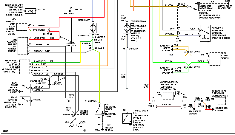
Three switches are found on the ignition switch. Each of the three switches transmits the battery’s current to a variety of places. The first switch provides power to the choke, while the second switch controls the on/off status of the ignition switch. Each manufacturer has their individual color-coding system that we will discuss in another article. OMC follows this method. The ignition switch comes with a connector for adding the timer.
Even though some ignition switch terminals don’t come in original form The numbering might not be in line with the diagram. Verify the electrical continuity first to ensure that they’re connected correctly to the ignition switch. This can be checked using a simple multimeter. After you’ve confirmed the integrity of the wires you can install the connector. The wiring loom for the ignition switch supplied by the manufacturer will differ from the one that you have in your vehicle.
Knowing how the ACC outputs connect to the other outputs inside your car is vital. The ACC and IGN terminals are the default connection on your ignition switch, and the START and IGN terminals are the principal connections for the stereo and radio. The ignition switch is responsible for turning the car’s engine on and off. The terminals of the ignition switch on older cars are identified with the initials “ACC” and “ST” (for the individual magneto wires).
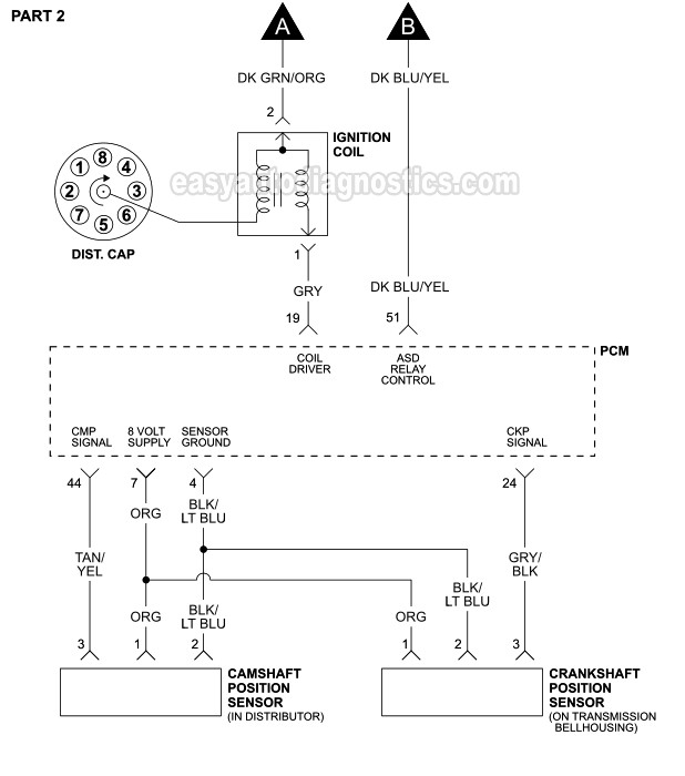
Terminals for coil
The first step in determining the kind of ignition coil is to know the terms employed. The basic ignition wiring diagram shows a number different connections and terminals. There are two primary and one secondary. Each coil has an operating voltage. The first step to determine which kind you’re using is to examine the voltage at S1 or the primary terminal. S1 must be tested for resistance in order to determine if the coil is type A, B or C.
The coil with low tension must be connected at the chassis’s plus. It is also the ground on an ignition wiring diagram. The high-tension part supplies positive direct to the sparkplugs. It is required for suppression purposes that the body of the coil’s metal be connected to its chassis however, it is not necessary. The wiring diagram for the ignition will explain how to connect the terminals of either the positive and negative coils. Sometimes, an inspection at an auto parts shop can identify a problem with the ignition wire.
The black-and-white-striped wire from the harness goes to the negative terminal. The positive terminal receives the other white wire, which has the trace of black. The black wire connects to the contact breaker. To check the connections, you can make use of a paperclip or pencil to remove them of the housing for the plug. Be sure to check that the terminals have not been bent.
Accessory terminals
Diagrams of the ignition wiring show the wires that supply power to different parts of the vehicle. Typically, there are four different colors-coded terminals that are used for each component. For accessories, red is for starter solenoid, yellow is for battery and blue for accessories. The “IGN terminal” is used to power the wipers as well as other operating functions. The diagram illustrates how you can connect ACC or ST terminals and the rest.
The terminal BAT is the connection to the battery. The battery is vital for the electrical system to get started. A dead battery can make the switch not come on. To find your car’s battery, check your wiring diagram. The accessory terminals in your vehicle are connected to the battery as well as the ignition switch. The BAT connector connects to your battery.
Some ignition switches are equipped with an accessory position. This lets users connect their outputs to a different place without having to turn on the ignition. Sometimes, users want to utilize an additional output that is independent of the ignition. The auxiliary output could be utilized by wiring the connector with the same color as your ignition, and then attaching it to the ACC terminal of the switch. Although this is a great feature, there’s one thing you should know. Most ignition switches will be in an ACC position when the vehicle is in the ACC however they will be at the START position when the vehicle is IGN.
Gallery of 1994 Dodge Dakota Ignition Wiring Diagram
Gallery of 1994 Dodge Dakota Ignition Wiring Diagram


