1998 Dodge Dakota Ignition Wiring Diagram – Let’s first examine the different kinds and functions of terminals found on the ignition switches. These include the terminals for the Ignition switch, Coil, and Accessory. Once we have identified the purpose of these terminals, we will be able to identify the various parts of the ignition wiring. We’ll also go over the roles of the Ignition switch and the Coil. Following that, we’ll shift our attention to the Accessory terminals.
Terminals of ignition switch
Three switches can be found on the ignition switch. Each of these switches feeds the battery’s voltage to various places. The first switch powers the choke. The second switch controls the ON/OFF of the ignition switch. Different manufacturers use their own color-coding systems for the various conductors, which is explained in a different article. OMC follows this system. The ignition switch comes with an option to connect a timer.
While the majority of ignition switch terminals don’t have an original number, they might be equipped with a different number. To ensure that your wires are properly connected to the switch, it is recommended to check their continuity. A multimeter is a good tool to check the continuity. After you’re satisfied with the connection, you can place the new connector. If your car has an original factory-supplied ignition switch (or a wiring loom) the wiring loom might differ from the one in the car.
Before connecting the ACC outputs to the auxiliary outputs of your car It is essential to know the fundamentals of these connections. The ACC/IGN terminals function as the default connections for the ignition switch. The START/IGN terminals connect to the radio or stereo. The ignition switch is the one that turns the car’s engine to and off. In older vehicles, the ignition switch terminals are marked with the letters “ACC” and “ST” (for individual magnet wires).
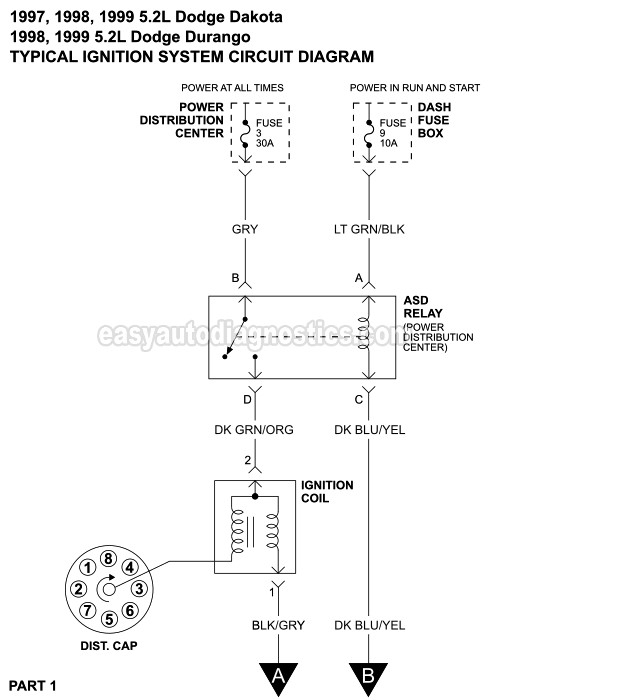
Terminals for coil
Understanding the terms utilized is the initial step towards finding out the right kind of ignition coil to choose. You’ll see a number of connections and terminals in an ignition wiring schematic which includes two primary and two secondary. Each coil has an operating voltage. The first step to determine the type you’re using is to examine the voltage at S1 or the primary terminal. S1 should be examined for resistance to determine if the coil is type A, B or C.
The low-tension end of the coil must be connected to the chassis”negative. This is the wiring diagram you will see on the wiring diagram. The high-tension side delivers positively direct to the spark plugs. To reduce the noise the body of the coil must be connected to the chassis. But, it’s not necessary to electrically connect. A wiring diagram can depict the connection between positive and negative coil terminals. Sometimes, a damaged ignition coil can be identified by a scan done at an auto repair shop.
The black-and-white-striped wire from the harness goes to the negative terminal. The positive terminal receives the white wire with the black trace. The black wire connects to the contactbreaker. You can check the connections with a pencil to pull the wires out of the housing. It is also important to see that the terminals aren’t bent.
Accessory terminals
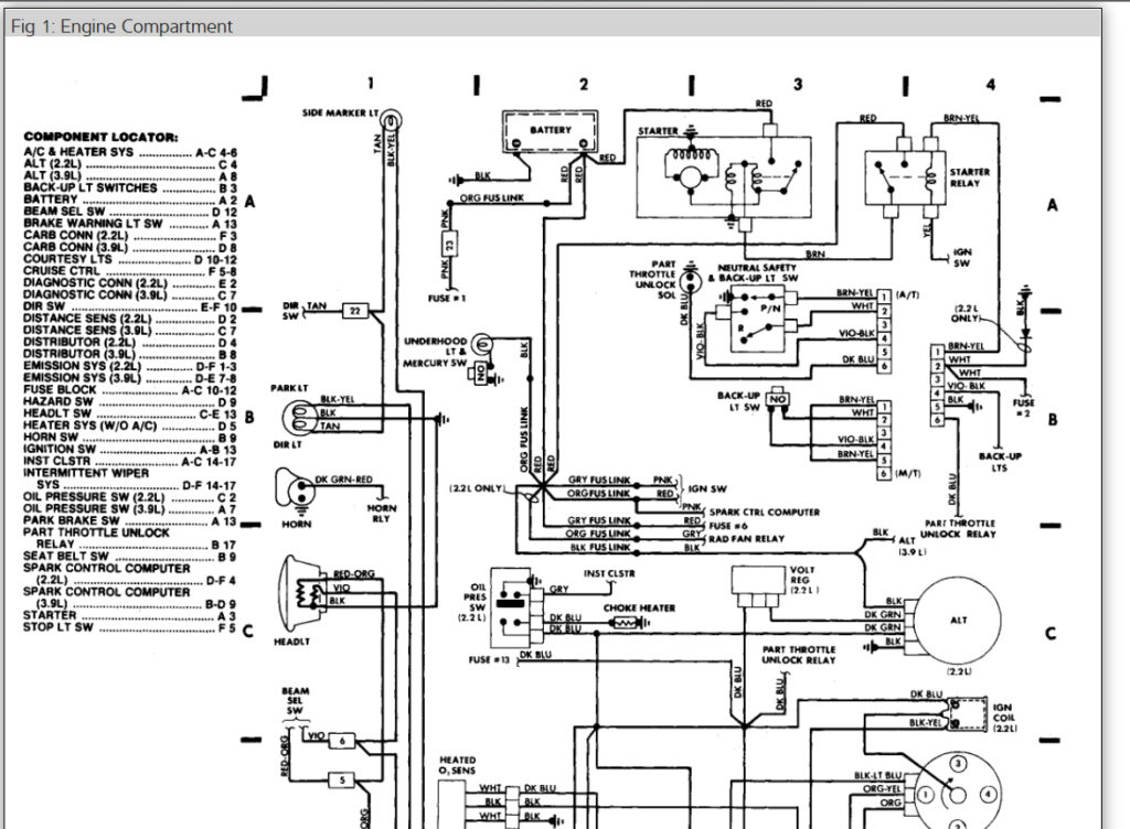
Diagrams of ignition wiring show the different wires that are used to power the car’s various components. Each part has four distinct colored connections. To identify accessories, red is for starter solenoid, blue for battery, and blue for accessory. The “IGN” terminal is utilized to turn on the car, operate the wipers and other features. This diagram demonstrates how to connect ACC and ST terminals with the rest of the components.
The terminal BAT holds the battery. The battery is necessary to allow the electrical system to get started. Also, the switch won’t be able to turn on without the battery. If you’re not sure the location of your car’s battery located, you can review the wiring diagram of your car to determine how to locate it. The accessory terminals of your car are connected to the battery and ignition button. The BAT terminal is connected to the battery.
Some ignition switches come with an additional “accessory position” that lets users adjust their outputs independently of the ignition. Customers sometimes want an auxiliary output that can be operated independently of the ignition. To allow the auxiliary output to be used, wire the connector in the same shade as that of the ignition. Then connect it with the ACC end of the switch. This is an excellent feature, however there’s one important distinction. The majority of ignition switches are designed to display an ACC status when the vehicle is at the ACC or START positions.
Gallery of 1998 Dodge Dakota Ignition Wiring Diagram
Gallery of 1998 Dodge Dakota Ignition Wiring Diagram


